Quick Leads
How to Calculate the Current Divider Formula in PCB Design: A Comprehensive Guide for Electrical Engineers
Introduction: The Importance of the Current Divider Formula in PCB Design
In electrical engineering, one of the key principles to understand is the Current Divider Formula. This formula is crucial for analyzing circuit behavior and optimizing PCB designs. Proper current distribution ensures that your PCB circuits operate efficiently, reducing the risk of overheating and signal interference.

In this article, we’ll guide you through the steps on how to calculate the Current Divider Rule in PCB design, emphasizing practical applications and advanced techniques like current flow optimization and circuit analysis in multilayer PCBs.
What is the Current Divider Rule?
The Current Divider Rule is a fundamental principle in electrical engineering that describes how current splits between two or more parallel components in a circuit. It allows you to calculate the current flowing through each parallel branch by considering the total current entering the parallel network and the resistances of the individual branches.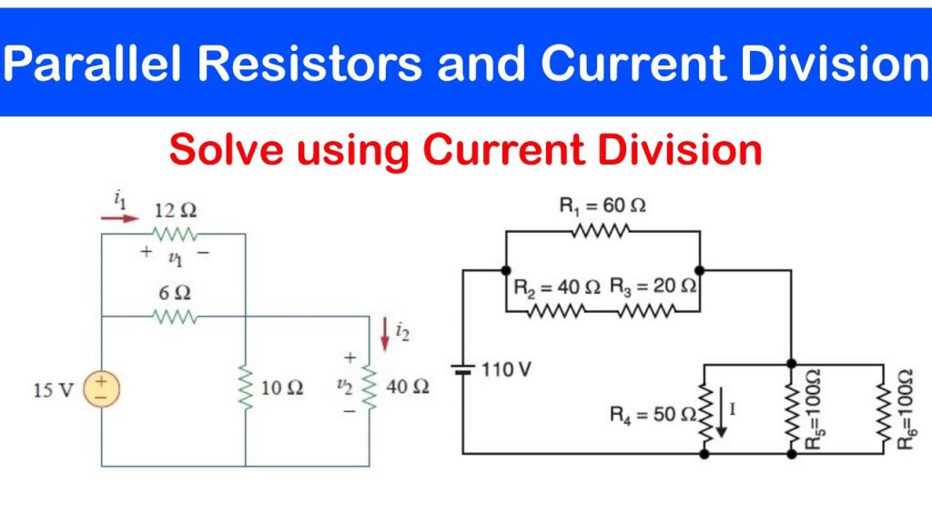
In a PCB design, understanding the Current Divider Rule is crucial for distributing current properly between the power and ground planes to prevent overheating and ensure efficient current distribution across the board.
Learn more about PCB Assembly Services on our PCB Assembly.
The formula for the Current Divider Rule is:I_n = I_t * (R_n / R_t)
Where:
- I_n: Current through the nth branch.
- I_t: Total current entering the parallel circuit.
- R_n: Resistance of the nth branch.
- R_t: Total resistance of the parallel circuit.
This rule is particularly useful for circuit analysis in multilayer PCBs and other complex designs, where efficient current flow is paramount for device functionality and reliability.
What is the Difference Between the Current Divider Formula and the Voltage Divider Formula?
While both the Current Divider Rule and the Voltage Divider Rule are used in parallel circuits, they address different aspects of current and voltage distribution.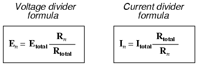
- Current Divider Rule: This formula calculates how the total current is divided among parallel branches based on their resistances. The total current entering the circuit splits across the parallel branches in inverse proportion to their resistances.For detailed calculations and examples, refer to our article on PCB Design Basics.
- Voltage Divider Rule: In contrast, the Voltage Divider Rule calculates how the total voltage is divided across components in series, not parallel. The voltage across each component in a series circuit is proportional to its resistance, relative to the total resistance.
- I_n = I_t * (R_n / R_t)
- V_n = V_t * (R_n / R_t)
Where:
- I_n: Current through the nth branch.
- V_n: Voltage across the nth component.
- I_t: Total current entering the parallel circuit.
- V_t: Total voltage applied to the series circuit.
- R_n: Resistance of the nth branch or component.
- R_t: Total resistance of the parallel or series circuit.
In summary:
- The Current Divider Rule is used for parallel circuits to divide current.
- The Voltage Divider Rule is used for series circuits to divide voltage. Both formulas are essential for circuit analysis, but they apply to different configurations and serve different purposes in electrical design.
What is the Procedure for Calculating Using the Current Divider Rule Formula?
Calculating current using the Current Divider Rule involves the following steps: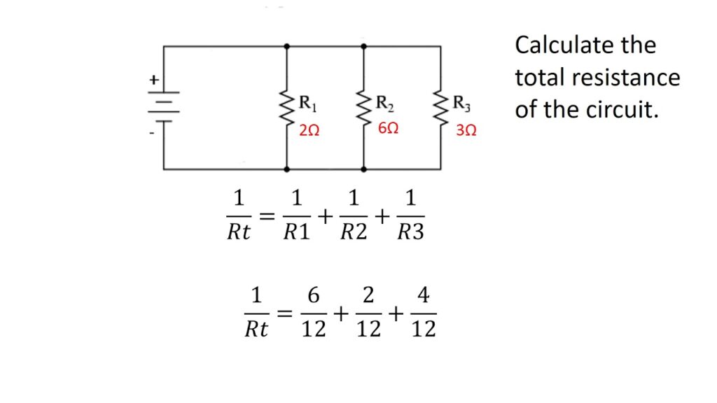
Step 1: Calculate the Total Resistance of the Parallel Circuit
For resistors in parallel, the total resistance R_t is calculated using the formula:R_t = 1 / (1/R_1 + 1/R_2 + … + 1/R_n)
This step is essential because the Current Divider Rule depends on knowing the total resistance in the parallel circuit.
Step 2: Apply the Current Divider Formula
Once you have the total resistance, apply the Current Divider Rule formula to find the current through each branch:I_n = I_t * (R_n / R_t)
Where:
- I_n is the current through the nth branch.
- I_t is the total current entering the parallel circuit.
- R_n is the resistance of the nth branch.
- R_t is the total resistance of the parallel branches.
This calculation gives you the current that flows through each parallel branch.

When Can You Use the Current Divider Rule Formula?
The Current Divider Rule can be applied in a variety of situations, particularly when designing or analyzing parallel circuits. Here are some common scenarios where the formula is especially useful:
Parallel Circuit Design:
The formula is ideal for calculating current distribution in parallel circuits, which are commonly found in PCB designs, where multiple components are connected to a single power source.Multilayer PCBs:
In multilayer PCB designs, efficient current distribution across power and ground planes is essential for reducing noise and ensuring consistent performance. The Current Divider Rule can help you balance currents across these planes to optimize signal integrity and thermal dissipation.Visit our Multilayer PCB Services for more information.Current Sharing in Power Supplies:
When multiple power supplies share the same load, the Current Divider Rule helps calculate how much current flows through each power supply. This is critical for load balancing and ensuring that each power supply operates within safe limits.Designing Power and Ground Planes in PCBs:
The Current Divider Rule helps distribute current evenly across the power and ground planes of the PCB, reducing the risk of thermal damage and improving overall circuit performance.Thermal Management:
The Current Divider Rule is also useful in optimizing the thermal management of high-power PCBs. By balancing the current across the parallel branches, you can prevent excessive heat buildup in one area, which could damage components or affect circuit performance.
Practical Applications of the Current Divider Formula in PCB Design
- Current Distribution in Multilayer PCBs In multilayer PCB designs, achieving uniform current distribution across power and ground planes is critical. Using the Current Divider Formula allows you to design the board so that current flow is optimized, reducing the chance of thermal hotspots and electrical interference.

Practical Tips for Current Distribution in PCB Design:
- Adjust Traces and Widths: Wider traces reduce resistance and help distribute current evenly across the PCB design.
- Optimize Ground Planes: Ensure that the ground plane has a low resistance, helping to improve the efficiency of current flow.
- Thermal Management: By applying current divider principles, you can enhance PCB heat dissipation and prevent excessive temperature buildup.
- Optimizing Heat Dissipation in High-Power Circuits
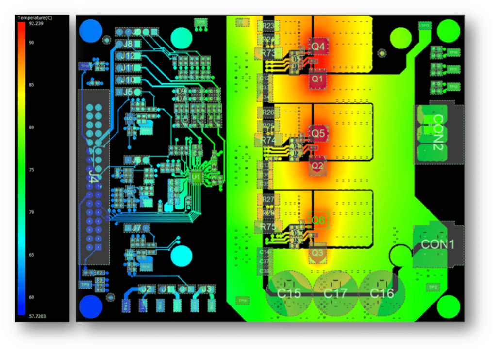
In high-power PCBs, managing heat is crucial. By leveraging the Current Divider Formula, you can ensure that current is distributed optimally, which helps reduce the risk of overheating and improves heat dissipation.
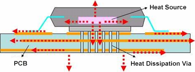
Tips for Efficient Heat Dissipation Using the Current Divider Formula:
- Widen High-Power Traces: Wider traces reduce current density and thus prevent excessive heat buildup.
- Add Thermal Vias: Distribute heat more evenly across layers, improving thermal management and circuit reliability.
- High-Frequency PCB Design Considerations
For high-frequency PCB designs, the Current Divider Formula helps ensure that current is distributed properly, minimizing the effects of parasitic inductance and capacitance. This is essential for maintaining signal integrity in high-speed circuits.
High-Frequency PCB Design Tips:
- Use Shorter Traces: Reduces inductance and improves current distribution.
- Control Parasitic Effects: Keep the traces as far apart as necessary to reduce parasitic capacitance.
Case Studies: How the Current Divider Formula Enhances PCB Performance
- Case Study 1: Balancing Current in LED Arrays In LED arrays, current needs to be evenly distributed for consistent brightness. Using the Current Divider Formula, you can calculate the current through each LED branch, ensuring uniform performance.
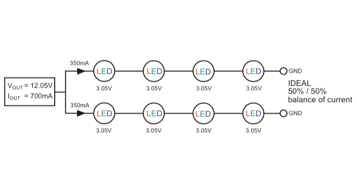
Steps to Balance Current:
Given I_t = 1A, R_1 = 10Ω, R_2 = 5Ω, calculate the total resistance:
R_t = 1 / (1/10 + 1/5) = 3.33Ω
Apply the formula to calculate the current through each branch:
I_1 = I_t * (R_1 / R_t) = 1 * (10 / 3.33) = 0.33A
I_2 = I_t * (R_2 / R_t) = 1 * (5 / 3.33) = 0.67A
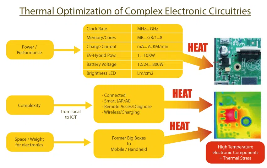
Case Study 2: Thermal Optimization in High-Power PCB Designs
When working with high-power PCBs, you can optimize current flow and prevent overheating by adjusting trace widths and applying the Current Divider Formula.
Resources for Electrical Engineers and PCB Designers
- Online Calculators and Tools
- Downloadable Resources
- Interactive Visuals
- Check out this interactive current flow simulation: View Demo.
Frequently Asked Questions
The Current Divider Formula is used to calculate how current splits across parallel branches in a circuit, while the Voltage Divider Formula determines how voltage is distributed across components in series circuits. Both are essential for circuit analysis but apply to different circuit configurations.
The Current Divider Formula helps ensure proper current distribution in PCBs, which reduces the risk of overheating, improves signal integrity, and optimizes overall circuit performance. This is especially critical in multilayer and high-power PCB designs.
To calculate the total resistance of a parallel circuit, use the formula: R_t = 1 / (1/R_1 + 1/R_2 + ... + 1/R_n) This is a key step before applying the Current Divider Formula to find the current in each branch.
By balancing current across parallel branches, the Current Divider Formula prevents excessive heat buildup in specific areas of the PCB. Wider traces and thermal vias can further optimize heat dissipation, ensuring circuit reliability in high-power applications.
Conclusion: The Impact of the Current Divider Formula in PCB Design
Mastering the Current Divider Formula is essential for electrical engineers and PCB designers. Whether you’re working with parallel circuits, optimizing current distribution, or tackling high-frequency signal challenges, applying this formula leads to more efficient, reliable, and well-optimized PCB designs.Limited Time Offer:
Get $100 off your order TODAY!
 Trusted by 100+ businesses worldwide
 No hidden fees – transparent pricing
 Guaranteed quality with on-time deliver
Request for Quote
RECENT POSTS

Top 10 EMS Providers Supporting Direct-to-Consumer Shipping (D2C)
Discover top D2C EMS providers offering low MOQ PCB assembly, turnkey manufacturing, and global shipping.

Top 15 Full-Service PCBA Suppliers for OEM Electronics in 2025 [Global List]
Discover 2025’s top full-service PCBA suppliers for OEM electronics. Compare global partners, solve sourcing pain
RELATED POSTS
Leading PCBA Manufacturer
✅ Assemble 20 PCBAS for $0 ✅ Get $100 OFF – Risk-Free Trial!
✅ 100+ Satisfied Customers
✅ Ensured Quality & On-Time Delivery
✅ Free Trial, No Commitments!


