
 Trusted by 100+ businesses worldwide No hidden fees – transparent pricing Guaranteed quality with on-time deliver
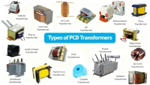
PCB Transformer Explained: Types, Working Principle, and Design Tips
Discover how PCB transformers work, their key types, and design integration tips. Learn to select
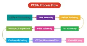
Why Smart OEMs Avoid Cheap PCB Assembly: 5 Hidden Risks That Cost More
Avoid costly mistakes in OEM projects. Discover why cheap PCB assembly risks quality, compliance, and