Quick Leads
Capacitor Symbols: A Guide to Understanding
Capacitors are one of the most essential components in electronics, appearing in almost every circuit design. But without a solid understanding of their symbols, engineers and decision-makers risk misinterpreting critical details during PCB assembly. This guide dives deep into capacitor symbols, explaining their types, meanings, and significance in PCB workflows, helping you confidently navigate circuit diagrams.
What Do the Symbols Mean on a Capacitor?
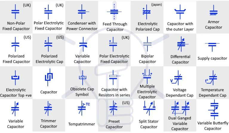
Capacitors are represented by symbols that describe their type, polarity, and functionality. The most common representations include:
- Fixed Capacitors:
These are depicted by two parallel lines of equal length, symbolizing the capacitor’s two conductive plates. Fixed capacitors can be either:- Non-polarized: The two parallel lines are identical, indicating the capacitor can be connected in either direction.
- Polarized: One line is straight (positive terminal), and the other is curved (negative terminal). This distinction is critical for components like electrolytic capacitors that must be installed in the correct orientation to avoid failure.
- Variable Capacitors:
Represented by a standard capacitor symbol with a diagonal arrow across it, variable capacitors allow engineers to adjust capacitance values during operation. These are commonly used in applications like radio frequency tuning. - Trimmer Capacitors:
A subtype of variable capacitors, trimmer capacitors are symbolized similarly but often include a small bar or screw-like mark, denoting adjustability with precision tools.
Each variation in these symbols ensures that engineers can quickly identify capacitor types, improving the efficiency of PCB design and manufacturing.
What Do K and J Mean in a Capacitor?
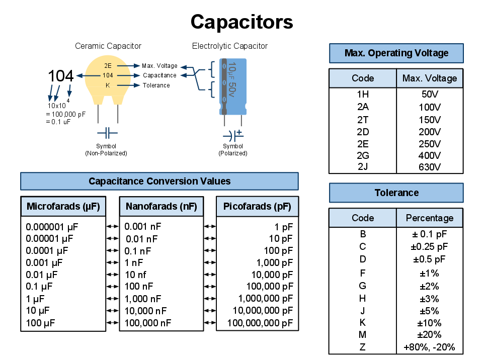
Capacitor markings, including letters like K and J, provide crucial information about tolerance—the permissible variation in the capacitance value from its nominal rating. For example:- K: Indicates a tolerance of ±10%.
- J: Indicates a tighter tolerance of ±5%.
Example in Practice:
If you select a 100 µF capacitor marked with a “K,” the actual capacitance could vary between 90 µF and 110 µF. Tighter tolerances, such as “J,” are more critical for high-precision circuits, such as filters or timing applications. These tolerances ensure engineers select capacitors suited to the operational requirements of their designs.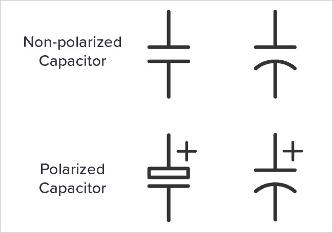
Which Side of a Capacitor Symbol Is Positive?
For polarized capacitors, the positive terminal is always represented by a straight line in the schematic symbol. This side often carries a “+” sign to emphasize the correct orientation. The curved line, on the other hand, marks the negative terminal.
In physical components:
- The positive terminal is typically the longer lead.
- The negative terminal is marked by a stripe on the capacitor body.
Why Polarity Matters:
Installing a polarized capacitor incorrectly can lead to catastrophic failure, including overheating or even explosions. This is especially true for electrolytic capacitors, which are sensitive to voltage reversal.
What Does C Stand for on a Capacitor?
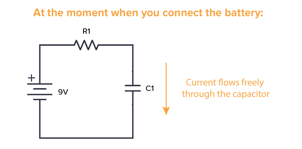
In circuit diagrams, the letter C denotes capacitance, the fundamental property of capacitors. It represents the component’s ability to store electrical charge and is measured in units of farads (F), often expressed in smaller denominations:- Microfarads (µF): Common for electrolytic capacitors.
- Nanofarads (nF): Used in ceramic and film capacitors.
- Picofarads (pF): Ideal for high-frequency applications.
Capacitance in Action:
For example, in power supply circuits, capacitors with high capacitance (measured in µF) are used to smooth voltage fluctuations, ensuring steady operation of sensitive electronic devices.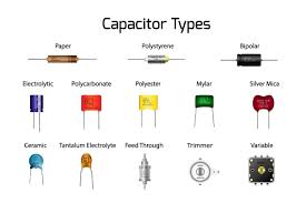
Overview of Capacitor Types
Different applications call for specific capacitor types. Here’s a breakdown of the most common options:
- Electrolytic Capacitors:
- Symbol: Straight line (positive terminal) and curved line (negative terminal).
- Use Case: Ideal for applications requiring high capacitance, such as power supply filtering.
- Advantages: High capacitance in a small package.
- Limitations: Limited lifespan and sensitivity to polarity.
- Ceramic Capacitors:
- Symbol: Two straight parallel lines of equal length.
- Use Case: High-frequency circuits and decoupling applications.
- Advantages: Stable, reliable, and non-polarized.
- Limitations: Lower capacitance compared to electrolytic capacitors.
- Variable Capacitors:
- Symbol: Two parallel lines with a diagonal arrow.
- Use Case: Frequency tuning in radios and oscillators.
- Advantages: Adjustable capacitance for dynamic applications.
- Limitations: Requires manual adjustment.
- Film Capacitors:
- Symbol: Identical to ceramic capacitors.
- Use Case: High-stability applications, such as audio circuits.
- Advantages: Excellent precision and durability.
- Limitations: Larger size for equivalent capacitance.
For more insights you can read this: Introduction to Capacitors
How to Read Capacitor Symbols in Circuit Diagrams
Understanding capacitor symbols in schematics is vital for accurate design and troubleshooting. Here’s how to approach it:- Identify the Type: Look for variations in the symbol, such as curved lines (polarized) or arrows (variable).
- Note the Capacitance Value: Typically displayed near the symbol (e.g., “10 µF”).
- Check Voltage Ratings: Some designs may include the voltage limit, such as “50V.” This ensures safe operation within the circuit’s parameters.
Example:
In a circuit diagram for an audio amplifier, you might see a capacitor symbol labeled “47 µF, 16V.” This indicates a polarized electrolytic capacitor with a capacitance of 47 microfarads and a maximum voltage rating of 16 volts.Importance of Capacitor Symbols in PCB Assembly
Capacitor symbols play a critical role throughout the PCB manufacturing process:
- Design Phase: Accurate symbols ensure that engineers select the correct components and polarities, reducing design errors.
- Sourcing Phase: Decision-makers can match capacitor requirements with available stock, avoiding mismatched or underspec components.
- Assembly Phase: Manufacturers rely on clear schematics to place components accurately, ensuring reliable circuit operation.
By mastering capacitor symbols, you can ensure a smoother workflow and higher-quality PCBs.
Practical Tips for Engineers and Decision-Makers
- Verify Component Specifications: Always cross-check schematic symbols with component datasheets to ensure compatibility.
- Understand Tolerance Requirements: For critical applications, select capacitors with tighter tolerances (e.g., “J” for ±5%).
- Prioritize High-Quality Components: Investing in reliable capacitors reduces the risk of failure during operation.
- Leverage Design Software: Many modern PCB tools provide built-in libraries for capacitor symbols, streamlining the design process.
Frequently Asked Questions
The symbol indicates the type (fixed, polarized, or variable) and orientation of the capacitor, ensuring proper installation and operation.
The straight line represents the positive terminal, while the curved line (or unmarked side) represents the negative terminal.
K and J indicate tolerances: K = ±10%, J = ±5%, helping engineers choose components with appropriate precision.
Capacitor markings provide capacitance (in µF, nF, or pF), voltage ratings (e.g., 50V), and tolerances, which are key for selecting the right component.
Limited Time Offer:
Get $100 off your order TODAY!
 Trusted by 100+ businesses worldwide
 No hidden fees – transparent pricing
 Guaranteed quality with on-time deliver
Summary
Understanding capacitor symbols is essential for engineers and decision-makers in PCB assembly. From interpreting schematic diagrams to selecting the right components, this knowledge is invaluable for ensuring accurate designs and reliable performance. By mastering capacitor types, markings, and practical applications, you can confidently tackle any circuit design challenge.
If you’re ready to optimize your PCB designs or need assistance sourcing components, don’t hesitate to reach out—let’s make your next project a success!
Have Specific Requirements?
We’re here to help! Whether it’s a custom PCB design, assembly, or sourcing components, feel free to reach out to us directly. Our team is ready to provide tailored solutions for your project. Contact Us Today for more information.
Additional Resources:
- How to Repair Circuit Boards: A Step-by-Step Beginner’s Guide
- Capacitor on Circuit Board: A Comprehensive Guide
- What Are PCB Conformal Coatings? Types, Benefits, and Applications Explained
- SMD Size Codes Explained: A Complete Guide to Understanding Surface-Mount Component Dimensions
- AC vs DC: Key Differences, Applications, and Advantages in Modern Electronics
Request for Quote
RECENT POSTS

PCB Transformer Explained: Types, Working Principle, and Design Tips
Discover how PCB transformers work, their key types, and design integration tips. Learn to select

Why Smart OEMs Avoid Cheap PCB Assembly: 5 Hidden Risks That Cost More
Avoid costly mistakes in OEM projects. Discover why cheap PCB assembly risks quality, compliance, and
RELATED POSTS
Leading PCBA Manufacturer
✅ Assemble 20 PCBAS for $0 ✅ Get $100 OFF – Risk-Free Trial!
✅ 100+ Satisfied Customers
✅ Ensured Quality & On-Time Delivery
✅ Free Trial, No Commitments!
