Quick Leads-PCBA
 Looking for full-service PCB Assembly?
Turnkey solutions from PCB manufacturing to testing.
sales@unitcircuits.com
🟢Let’s Talk About IC Boards – The Brains Behind Every Smart Product
Whether you’re building an embedded device, a wearable, or a high-speed router, the IC board is what brings everything to life. But here’s the problem: as integrated circuits become smaller, denser, and more complex, designing and assembling these boards has become a real headache — especially for engineers dealing with tight deadlines, low-volume orders, or sourcing challenges.
In this guide, I’ll break down what IC boards are, where they’re used, how to design them properly, and how we help companies like yours avoid common manufacturing pitfalls.
🟡What Is an IC Board?
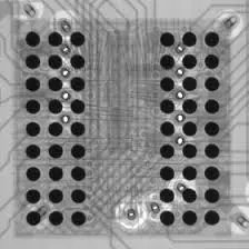
An IC board is a printed circuit board specifically designed to host integrated circuits (ICs) — these could be microcontrollers, FPGAs, power management chips, or custom ASICs. Unlike simpler boards that mostly handle passive components, IC boards tend to be more dense, layered, and thermally sensitive.
They’re everywhere — powering your phone’s touchscreen, running your car’s ECU, and connecting IoT devices to the cloud. An integrated circuit (IC) is a compact chip that performs logic or analog functions within a system. Learn more about how ICs work here.
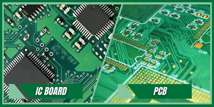
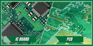
IC Board vs. Regular PCB: What’s the Difference?
| Feature | IC Board | General PCB |
|---|---|---|
| Component Density | High (QFP, BGA, LGA, QFN) | Moderate (resistors, connectors) |
| Thermal Needs | Needs active/passive heat relief | Often passive only |
| Design Complexity | Tight trace tolerances, multiple layers | Simpler 2-4 layer routing |
| Assembly Method | Mainly SMT + selective THT | Mix of THT and SMT |
| Applications | Embedded, IoT, AI, RF | Power, switching, basic control |
So while every IC board is a PCB, not every PCB is an IC board. While every IC board is technically a PCB, the real value is created during assembly. Understanding the difference between a bare PCB and a fully assembled PCBA is critical when working with IC-heavy designs. This guide on what PCBA is and how it differs from PCB explains why assembly quality directly affects IC reliability, yield, and long-term performance.
🔹Where Are IC Boards Used?
Let’s look at a few real-world examples:
🛠️ Embedded Systems and IoT Devices
Think microcontrollers, sensors, wireless modules. IC boards are used in:
Smart thermostats
Fitness bands
Smart locks and industrial gateways
These typically use IC boards for embedded systems, optimized for low power, compact footprints, and signal integrity.
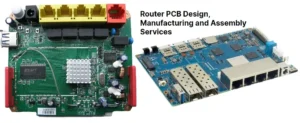
📡 High-Frequency Circuits
Boards used in RF communication, signal processing, or high-speed logic need careful layout. These require:
Short trace lengths
Impedance matching
Shielded ICs and connectors
Often used in high-frequency IC board applications like satellite modules, networking gear, and audio DSPs.
🔋 Power Supply IC Boards
Power management is a huge part of modern electronics. These boards focus on:
Step-down or boost converters (DC-DC)
Battery management ICs
Load switch ICs
You’ll find power supply IC boards inside everything from power banks to drones to medical devices.
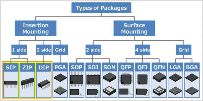
🧰 Common IC Packaging Types (And How They Mount)
One of the biggest challenges in IC board layout design is accounting for different IC packages. Let’s compare:
| Package Type | Pitch | Mounting Method | Common Use |
|---|---|---|---|
| DIP | Wide | Through-hole | Legacy, prototyping |
| QFP | Fine | Surface-mount | MCUs, DSPs, FPGAs |
| BGA | Very fine | Surface-mount | Processors, RAM |
| QFN | No leads | Surface-mount | RF, power ICs |
| LGA | Land grid | Surface-mount | CPUs, compute modules |
Each of these impacts:
The IC footprint
The PCB soldering process
The inspection strategy (especially for hidden joints under BGAs)
SMT vs THT for ICs: Which Should You Use?
SMT (Surface Mount Technology) dominates IC board design now, especially for SMT IC board assembly. It allows:
Smaller packages
Faster automated assembly
More compact layouts
But some applications still benefit from through-hole ICs:
Rugged environments (vibration resistance)
High-current paths
Easy hand-soldering for prototypes
Some IC boards with through-hole components use a hybrid approach — SMT for ICs, THT for power connectors or relays. Most modern IC boards rely heavily on SMT, but not every project is SMT-only. Choosing between surface-mount and through-hole assembly impacts cost, reliability, and inspection—especially for fine-pitch ICs. This SMT vs SMD vs THT comparison breaks down when each assembly method makes sense for IC board manufacturing.
Unit Circuits: Leading PCBA Manufacturer
 ISO-certified & 8+ years of PCBA Low MOQ & Fast Turnaround Prototype & Mass production
Limited Time Offer:
Get $100 off your order TODAY!
sales@unitcircuits.com
🔹Designing IC Boards: Layout Tips That Matter
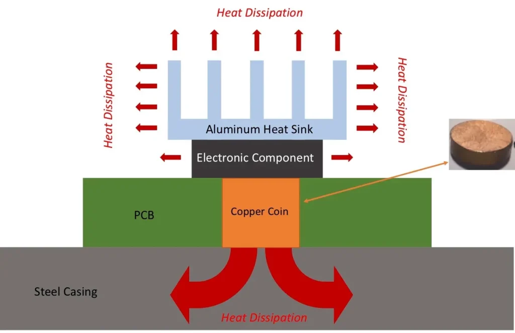
🔥 Thermal Management
High-density ICs produce heat. And heat kills performance — or worse, the board.
Tips:
Use thermal vias under IC pads
Add copper pours connected to ground
Space out high-power ICs
Consider adding thermal relief pads in the footprint
Use IC board thermal management techniques early in layout — not just as a patch job in revision B. Managing heat in dense IC layouts is essential. This guide from Analog Devices explains proven thermal design strategies for PCBs.
🧩 IC Placement Strategy
How you place components affects:
Trace lengths
Crosstalk
Decoupling efficiency
Best practices for component placement on IC boards:
Keep high-speed signals short and direct
Group related ICs (e.g. MCU and memory)
Keep analog/digital sections isolated
Place bypass capacitors close to VCC pins
🛤️ Routing and Layer Planning
For multi-layer IC boards, don’t skimp on layer count just to save cost.
Smart stacking:
Layer 1: Signal
Layer 2: Ground
Layer 3: Power
Layer 4: Signal / routing
Use wider traces for power rails, keep sensitive analog signals away from switching ICs, and always simulate high-speed traces when possible.
⚠️ Avoid Common Mistakes in IC Layout
These come up often during IC board DFM checks:
Wrong footprint used (BGA pads off by 0.2 mm!)
No thermal relief on power pins
Silkscreen over pads
Incomplete solder mask openings
A good IC board design tip: Run layout checks using your assembly house’s checklist — or let us review it before you hit “manufacture.”
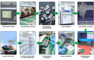
🔹How IC Board Assembly Really Works
Let’s go from design to done.
📁 1. Pre-Assembly Prep
Validate BOM against stock
Confirm IC board layout design
Design stencil for paste application
Review component orientation and polarity
This is where we catch early mistakes before they cost time.
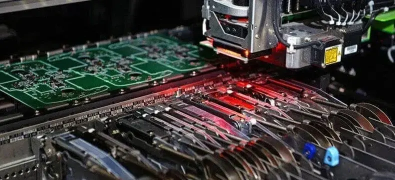
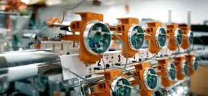
🤖 2. Pick and Place (SMT)
We program our machines for:
Precise IC chip mounting on PCB
QFN alignment via fiducials
Volume-accurate solder paste
SMT IC board assembly needs tight control to prevent tombstoning or cold joints — especially with small-pitch ICs.SMT enables precise IC mounting on modern PCBs. IEEE offers an overview of SMT technology and its role in electronics miniaturization.
♨️ 3. Reflow Soldering
The board goes through a temperature-controlled oven. The paste melts, then cools to form joints.
We use profile tuning for:
Lead-free or leaded solder
Heavy copper vs fine-pitch IC zones
Mixed-material boards
🔍 4. Inspection & Testing
We use:
AOI (automated optical inspection)
X-ray for BGA packages
Functional testing if test jigs are provided
These are essential steps in IC board testing methods — no one wants a dead MCU because of a hidden joint crack. High-density IC boards often use BGA packages, which hide solder joints beneath the chip. These designs demand precise layout rules and advanced inspection methods. This in-depth guide to BGA technology in PCB design explains footprint considerations, reflow challenges, and why X-ray inspection is essential for BGA-based IC boards.
⚠️ Real Industry Pain Points (And How We Solve Them)
❌ Problem: Fine-Pitch ICs Fail at Reflow
Even the best layout can fall short if the assembly house doesn’t handle 0.4 mm pitch QFNs properly.
✅ Our Solution: High-precision SMT lines, solder paste inspection, and reflow profiling tailored to your stack-up.
❌ Problem: Prototype Runs Cost Too Much
Big factories charge a fortune to build low volume IC boards or turn them down altogether.
✅ Our Solution: We specialize in low-volume, high-mix jobs — including stencil printing and rework support.
❌ Problem: DFM Revisions Delay Everything
You send your Gerbers out, and a week later you get a vague “can’t assemble this” reply.
✅ Our Solution: We offer free layout review + DFM feedback before any files go into production.
🔹Custom IC Board Manufacturing and Full Assembly Services
Here’s what we offer to keep your project moving:
🧪 Prototype to Production
Whether you’re building a one-off test rig or scaling into batches of 500, we handle:
-
PCB fabrication (2–12 layers)
-
Custom IC board manufacturing with fine-pitch footprint support
-
Sourcing of complex ICs (subject to global availability)
📦 Turnkey Services
We handle it all — sourcing, assembly, test, and packaging:
-
No need to send parts separately
-
We take responsibility for yield
-
Ideal for startups or agile teams building proof-of-concept hardware
📋 Fabrication Guidelines for IC Boards
Some reminders when designing for manufacturability:
-
Keep trace widths above 4 mil for standard fabs
-
Allow 10 mil spacing between SMT pads when possible
-
Watch PCB soldering for ICs — especially power ICs with large pads
We provide full PCB assembly guidelines and checklist for IC-heavy designs on request.
FAQs
1. What is an IC on a board?
An IC (Integrated Circuit) on a PCB is a compact semiconductor device that performs key functions like processing, memory, or power management. On an IC board, these chips are mounted using SMT or THT methods depending on design requirements. They form the “brain” of electronic products such as IoT modules, routers, and embedded devices.
2. How to understand the circuit board layout for ICs?
Understanding IC board layout starts with identifying power, ground, and signal traces, then locating the IC packages like BGA or QFN. Key things to consider include component placement, thermal relief, and high-speed signal routing. Beginners should review Gerber files and schematics alongside layout software like KiCad or Altium to gain a clearer picture.
3. What are the different types of ICs used in PCBs?
Common IC types on IC boards include microcontrollers (MCUs), memory ICs (RAM, Flash), power management ICs (PMICs), and signal ICs (op-amps, logic gates). High-speed applications use processors or FPGAs. Each IC has a specific package and footprint, so correct selection and placement are vital in IC board design and assembly.
4. How does an IC function in a circuit board?
An IC on a printed circuit board (PCB) works by receiving power and signals through its pins, performing logic or analog operations, and outputting results. Depending on the IC type, it might control voltage (regulators), process data (MCUs), or drive other components (gate drivers). Proper IC board layout ensures these operations are reliable and noise-free.
Have Specific Requirements?
Looking for high-precision PCB assembly for your products? Our team specializes in delivering top-tier assembly services, ensuring your devices perform flawlessly in any environment. Contact us today for a free consultation on how we can enhance your product’s reliability.
🟢 Conclusion: Build Better IC Boards with Smarter Support
IC boards are at the center of every smart product. But they come with their own set of design and assembly headaches — especially when working with fine-pitch ICs, power-sensitive designs, or low-volume production runs.
That’s why we don’t just build boards. We solve problems — from layout guidance to full IC board assembly service that supports your team from prototype to production.
📩 Need help building your next IC-based PCB? Get a Free Quote from Unit Circuits — and we’ll help you get to market faster, smarter, and with fewer revisions.
Save on your next PCB project?
Claim $100 OFF your order today.
sales@unitcircuits.com
✅ high-quality PCB assembly with strict quality control ✅ ISO-certified & 8+ years of experience. ✅ Low MOQ, fast turnaround, and 100% E-tested PCBs.
Additional Resources:
- How to Repair Circuit Boards: A Step-by-Step Beginner’s Guide
- Capacitor on Circuit Board: A Comprehensive Guide
- What Are PCB Conformal Coatings? Types, Benefits, and Applications Explained
- SMD Size Codes Explained: A Complete Guide to Understanding Surface-Mount Component Dimensions
- AC vs DC: Key Differences, Applications, and Advantages in Modern Electronics
Request for Quote
sales@unitcircuits.com
RECENT POSTS
IC Boards Explained: Applications, Layout Tips, and Assembly Services
Discover what IC boards are, how they’re used in modern electronics, and how to design
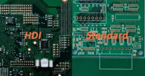
HDI PCB vs Multilayer PCB: How to Choose the Right One for Cost, Signal Integrity & Manufacturing
HDI PCB vs multilayer PCB explained from a manufacturing and assembly perspective. Learn how cost,
RELATED POSTS
Leading PCBA Manufacturer
✅ Assemble 20 PCBAS for $0 ✅ Get $100 OFF – Risk-Free Trial!
sales@unitcircuits.com
✅ 100+ Satisfied Customers
✅ Ensured Quality & On-Time Delivery
✅ Free Trial, No Commitments!