Quick Leads-PCBA
Ever wondered why some PCBs fail under stress while others thrive in extreme environments?
It all comes down to the materials. Choosing the right PCB base materials can make or break your product — literally. Let’s break down what PCBs are made of and how material selection impacts real-world performance.
PCBs are made of a non-conductive substrate (usually FR4 fiberglass), layered with copper foil to form conductive traces. These layers are bonded with epoxy resin, topped with a solder mask for insulation, and labeled using a silkscreen layer. Together, these materials create a durable, heat-resistant, and electrically optimized board for mounting and connecting components.
We’ll cover PCB material structure, selection, and advanced considerations. For a quick overview of the basics, check out our earlier guide on what PCBs are made of.
Now that we’ve nailed the basics, let’s explore PCB materials in-depth — from technical specs to sourcing tips, industry pain points, and how our services solve them.
What Does a PCB Contain? Inside the Layered Structure
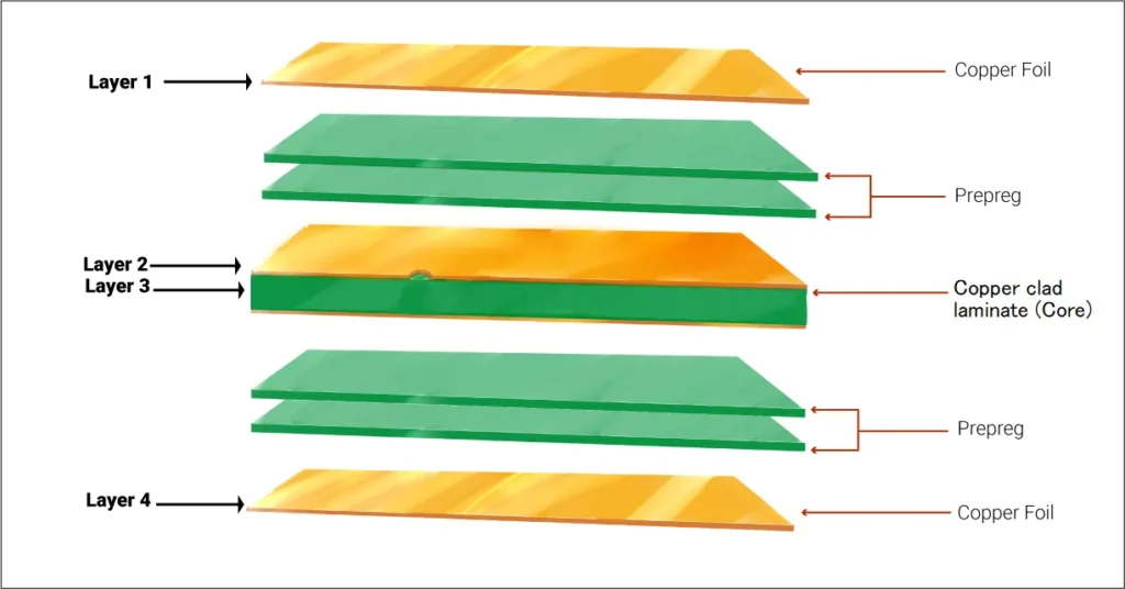
A PCB is like a sandwich — not the kind you eat, but one layered with precision. Here’s what goes into a standard PCB:
-
Substrate (core): Usually FR4, a fiberglass-reinforced epoxy laminate.
-
Copper layer(s): Conductive pathways etched into copper foil.
-
Prepreg (resin): Acts as glue and dielectric between layers.
-
Solder mask: Protects copper from oxidation and prevents solder bridges.
-
Silkscreen: Printed identifiers, logos, and reference markers.
If you’re working on multilayer PCBs, the stackup becomes even more critical — affecting impedance, EMI, and thermal performance.
Common PCB Materials: What Are They and Why Do They Matter?
PCB materials aren’t just about function — they’re about reliability, cost, and compliance.
| Material Type | Usage | Pros | Cons |
|---|---|---|---|
| FR4 (Epoxy + Fiberglass) | General-purpose PCBs | Cost-effective, decent thermal and mechanical strength | Limited for high-frequency or high-speed circuits |
| CEM-1 / CEM-3 | Low-end consumer electronics | Cheap and easy to process | Poor mechanical strength |
| Polyimide | Flexible PCBs | Excellent heat resistance, flexible | Expensive |
| Rogers (High-Freq) | RF/microwave circuits | Low dielectric loss, high frequency capable | Costlier, harder to process |
| Metal Core (MCPCB) | LED & power electronics | Superior heat dissipation | Limited flexibility |
FR4 PCB Material Properties: Why It’s the Industry Standard
FR4 is the most widely used PCB base material. Why? Because it balances price and performance.
Key FR4 properties:
-
Dielectric constant (Dk): ~4.5
-
Glass Transition Temperature (Tg): 130–180°C
-
Thermal conductivity: ~0.3 W/mK
-
Flame retardant & ROHS compliant
But not all FR4 is equal — cheap variants cause delamination or warping in reflow soldering. We only source high-grade FR4, verified to meet IPC standards.
While FR4 remains the go-to standard, comparing it with alternatives like aluminum core PCBs is essential for thermal-heavy designs. Here’s a detailed guide on FR4 vs. aluminum PCBs that engineers often reference.
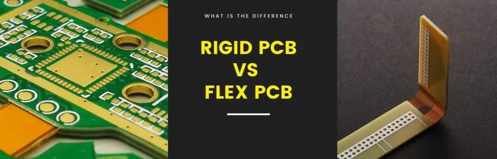
Flexible vs. Rigid PCB Materials: Which One’s Right for Your Project?
Choosing between flexible and rigid PCBs depends on the application.
| Feature | Rigid PCBs | Flexible PCBs |
|---|---|---|
| Material | FR4, CEM-1, Rogers | Polyimide, PET |
| Durability | High | Moderate (depends on bend radius) |
| Cost | Lower | Higher |
| Use Case | Most electronics | Wearables, aerospace, medical |
We often recommend rigid-flex designs for devices that require both high-density interconnects and flexibility.
A Quick PCB Material Comparison Chart
| Material | Tg (°C) | Dk | Flexibility | RoHS Compliant | Typical Use |
|---|---|---|---|---|---|
| FR4 | 130-180 | ~4.5 | No | Yes | Consumer electronics, IoT |
| Polyimide | >200 | ~3.5 | Yes | Yes | Automotive, aerospace, flex PCBs |
| Rogers RO4350 | ~280 | ~3.5 | No | Yes | RF applications |
| Aluminum MCPCB | N/A | N/A | No | Yes | LED lighting, power circuits |
Unit Circuits: Leading PCBA Manufacturer
 ISO-certified & 8+ years of PCBA Low MOQ & Fast Turnaround Prototype & Mass production
Limited Time Offer:
Get $100 off your order TODAY!
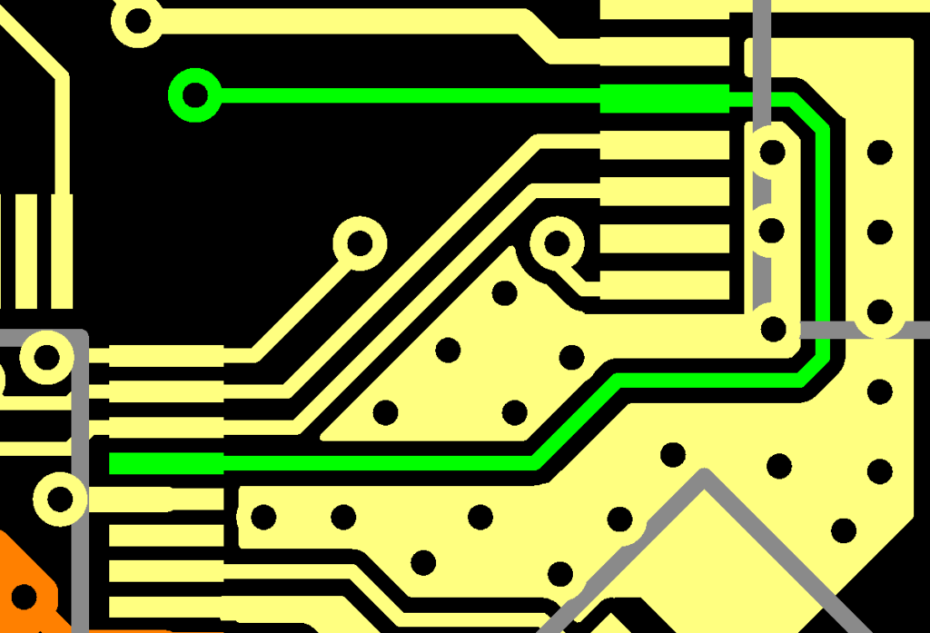
What Are PCB Traces Made Of? Copper and Alternatives
Traces are made of etched copper. Copper thickness is measured in ounces — 1oz = ~35 microns.
Key trace materials:
-
Standard copper foil: Most common, used in 1oz or 2oz thickness.
-
Heavy copper: Used for power electronics (up to 12oz).
-
Silver ink: Used in printed electronics but rarely in multilayer PCBs.
Why does it matter? Trace width and copper thickness affect current carrying capacity, heat dissipation, and signal integrity.
Copper Thickness 1oz vs 2oz: Which One Should You Choose?
Choosing between 1oz and 2oz copper impacts power handling and manufacturing cost.
| Feature | 1oz Copper | 2oz Copper |
|---|---|---|
| Cost | Lower | Higher |
| Current Capacity | Moderate | Higher |
| Trace Width Needed | Wider for same amp | Thinner for same amp |
| Etching Tolerance | Higher | Requires tighter control |
Use 2oz copper when designing power supply boards or motor drivers.
Understanding PCB Substrate Types and Their Applications
The substrate is your foundation. It holds everything together and impacts thermal and electrical behavior.
Types of substrates:
-
FR4: Default choice for most boards.
-
Polyimide: Used in flex PCBs due to heat resistance.
-
PTFE (Teflon): RF boards.
-
Metal Core: Aluminum or copper core for high power.
We offer custom stackups tailored to your substrate and performance needs.
Learn more about how prepreg and core materials influence board performance and manufacturing in this detailed engineering guide.
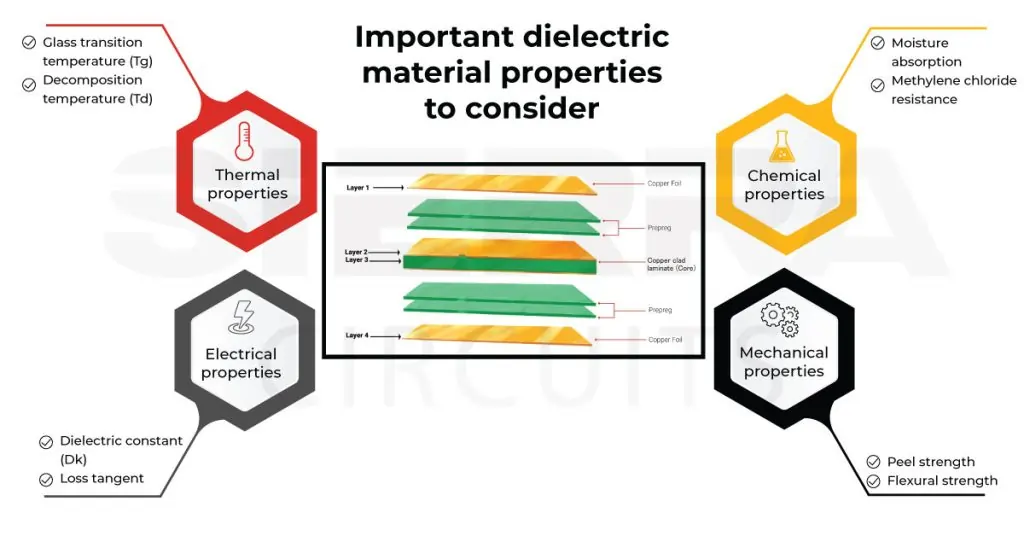
Thermal Conductivity, Tg Value & Signal Integrity: The Technical Trio
If you’re designing for high-speed signals or high temps, pay close attention to:
-
Thermal Conductivity (W/mK): Impacts cooling.
-
Tg Value: Above this temperature, the board becomes soft and unstable.
-
Signal Integrity: Impacted by dielectric loss and trace geometry.
We provide simulation support for impedance control, dielectric analysis, and thermal profiling.
If you’re building PCBs for extreme heat environments, material choice is non-negotiable. Here’s a breakdown of the best PCB materials for high-temperature applications.
Solder Mask vs Silkscreen: Not Just for Looks
-
Solder Mask: Prevents solder bridges and oxidation. Usually green but we offer red, blue, black, white.
-
Silkscreen: Printed layer showing reference designators. Crucial for assembly and debugging.
High-quality printing = fewer mistakes during assembly.
Lead-Free PCB Materials & ROHS Compliance: Staying Ahead of Regulations
If you’re selling in Europe or the U.S., your boards must be ROHS compliant.
We only use:
-
Lead-free solder (SAC305)
-
Halogen-free laminates (when required)
-
Certified materials under IPC-4101C
Let us handle compliance so you don’t have to worry about audits later.
Halogen-Free & Low-Cost PCB Materials: Are They Worth It?
Halogen-free PCBs are gaining ground in automotive and consumer tech — not only eco-friendly, but also flame-retardant.
Low-cost materials (like CEM-1) are okay for low-end toys or gadgets, but for industrial or wearable tech, go with FR4 or better.
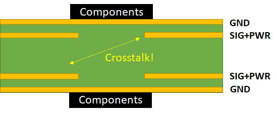
PCB Stackup Design: The Backbone of Multilayer Boards
The stackup defines layer order, impedance control, and interference shielding. Poor stackups = crosstalk, EMI, overheating.
We help clients design:
-
4–12+ layer boards
-
Controlled impedance
-
Power/GND planes
-
Thermal vias
Pain Points in PCB Assembly: Where Things Go Wrong
Let’s be real — the industry is full of pain points:
Material mismatches during prototyping vs production
Warped boards due to low Tg FR4
Delayed BOM sourcing
No transparency in quote timelines
MOQs that don’t fit R&D budgets
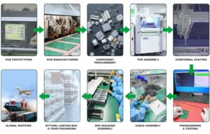
How Our Turnkey PCB Assembly Services Solve Real-World Issues
Here’s how we’ve helped engineers like you:
✅ No MOQ — perfect for prototyping or pilot runs.
✅ Fast PCB quote online — no back-and-forth emails.
✅ Verified materials — every batch inspected and documented.
✅ In-house assembly — surface-mount, through-hole, mixed.
✅ Sourcing support — we manage part shortages & alternates.
No MOQ PCB Manufacturing & Fast Online Quote: Why Engineers Love Us
You want to move fast. We get it.
Instant pricing? ✔️
Upload Gerbers & BOM in one step? ✔️
Track your order from fab to shipping? ✔️
Our platform is built for designers, startups, and OEMs alike.
Choosing the Best PCB Material for Prototyping
Start with standard FR4 unless:
You’re building RF or high-speed digital circuits → Rogers
You need bendable boards → Polyimide
You’re testing power circuits → MCPCB
Need help? We offer free DFM review before production.
FAQs
1. What is the standard PCB material used today?
The most common material for printed circuit boards is FR4, a fiberglass-reinforced epoxy laminate. It’s reliable, cost-effective, and ideal for most consumer and industrial applications. Standard PCB materials like FR4 offer a balance of thermal resistance, mechanical strength, and signal performance. If your application involves high frequency or heat, we also support Rogers, polyimide, and metal core substrates.
2. What are PCB traces made of and why does it matter?
PCB traces are typically made of copper, either 1oz or 2oz thick, depending on your current and heat requirements. These copper traces connect components and affect signal integrity and thermal conductivity. Poor-quality copper or incorrect trace width can lead to overheating or interference. We help you optimize trace specs for high-speed designs and power circuits alike.
3. What does a PCB consist of and how does that impact durability?
A typical PCB consists of several layers: a substrate (usually FR4), copper foil, prepreg resin, solder mask, and silkscreen. The composition of a PCB board directly affects its durability, performance under heat, and flexibility. We use only IPC-rated and ROHS compliant materials to ensure long-term reliability in both prototyping and mass production.
4. What's the difference between a printed wiring board and a printed circuit board?
There’s a subtle distinction: a printed wiring board (PWB) refers to the bare board with just traces and no components, while a printed circuit board (PCB) includes both the board and mounted parts. However, in modern usage, PCB is the standard term. Whether you need bare boards or full turnkey PCB assembly, we’ve got you covered.
Have Specific Requirements?
Looking for high-precision PCB assembly for your products? Our team specializes in delivering top-tier assembly services, ensuring your devices perform flawlessly in any environment. Contact us today for a free consultation on how we can enhance your product’s reliability.
IPC Standards and Material Certifications: What You Need to Know
All boards meet or exceed:
IPC-A-600 Class 2 or Class 3
UL94 V-0 Flame rating
ISO 9001 / IATF 16949 (for automotive clients)
How to Select PCB Materials in SOLIDWORKS or Other Design Tools
When using tools like SOLIDWORKS, Altium, or Eagle:
Choose from material libraries
Match substrate, copper thickness, and dielectric values
Export stackup documentation for manufacturers
Need help integrating your stackup into SOLIDWORKS? Just ask — our engineers assist at no extra cost.
Types of PCB Materials PDF & Laminate Selection Guide
PCB Materials Guide (PDF)
Laminate Selection Cheat Sheet
Impedance & Stackup Templates
Let’s Wrap It Up
PCB materials aren’t just specs — they’re strategic decisions. Whether you’re prototyping or mass-producing, the right material boosts reliability and cost-efficiency. Have questions or need a fast quote? Let’s talk!
Save on your next PCB project?
Claim $100 OFF your order today.
✅ high-quality PCB assembly with strict quality control ✅ ISO-certified & 8+ years of experience. ✅ Low MOQ, fast turnaround, and 100% E-tested PCBs.
Additional Resources:
- How to Repair Circuit Boards: A Step-by-Step Beginner’s Guide
- Capacitor on Circuit Board: A Comprehensive Guide
- What Are PCB Conformal Coatings? Types, Benefits, and Applications Explained
- SMD Size Codes Explained: A Complete Guide to Understanding Surface-Mount Component Dimensions
- AC vs DC: Key Differences, Applications, and Advantages in Modern Electronics
Request for Quote
RECENT POSTS
IC Boards Explained: Applications, Layout Tips, and Assembly Services
Discover what IC boards are, how they’re used in modern electronics, and how to design
HDI PCB vs Multilayer PCB: How to Choose the Right One for Cost, Signal Integrity & Manufacturing
HDI PCB vs multilayer PCB explained from a manufacturing and assembly perspective. Learn how cost,
RELATED POSTS
Leading PCBA Manufacturer
✅ Assemble 20 PCBAS for $0 ✅ Get $100 OFF – Risk-Free Trial!
✅ 100+ Satisfied Customers
✅ Ensured Quality & On-Time Delivery
✅ Free Trial, No Commitments!