Quick Leads
What Are USB Pinouts and Why Are They Crucial for Your Devices?
What Are USB Pinouts?
USB pinouts refer to the arrangement of pins inside a USB connector that define how power and data flow between devices. Depending on the type of USB connector (Type-A, Type-B, USB-C, etc.), the pinout varies. The general idea remains the same: there are power (VCC), ground (GND), and data pins (D+ and D-) that allow devices to exchange power and information. Understanding these pinouts ensures that your USB-based systems work efficiently, reduces the risk of electrical faults, and helps you troubleshoot more effectively. The importance of USB pinouts cannot be overstated. The pinout dictates how devices interact with each other, how power is supplied, and how data is transferred. It also helps in designing custom USB connections, debugging hardware issues, and ensuring smooth integration between USB peripherals.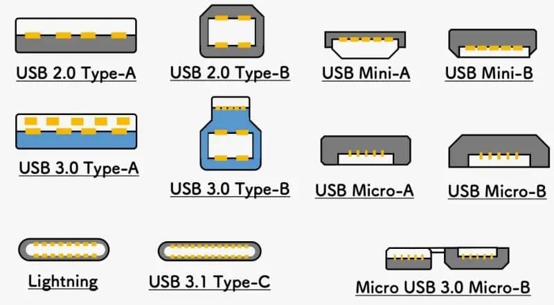
What Are the Different Types of USB Connectors?
1. USB Type-A
The most common USB connector, Type-A, is found on many devices, including desktops, laptops, and peripheral devices such as keyboards and mice. Type-A connectors are rectangular, with four pins used for data and power. USB Type-A pinout typically includes:
- VCC (Power)
- Ground (GND)
- Data+ (D+)
- Data- (D-)
Usage: Type-A connectors are designed primarily for host devices, such as computers, that supply power to connected peripherals. Type-A connectors are most commonly seen in USB 2.0 and USB 3.0 implementations, with USB 3.0 adding additional pins for higher data transfer rates.
2. USB Type-B
USB Type-B connectors are often used in larger devices like printers, scanners, and external hard drives. The connector is squarish with beveled edges. USB Type-B pinout typically includes the same four pins as Type-A but differs in its shape and orientation. The physical design of Type-B is meant to prevent incorrect connections.
- VCC (Power)
- Ground (GND)
- Data+ (D+)
- Data- (D-)
Usage: USB Type-B connectors are commonly found on peripherals that need to receive power and transfer data to a host computer. While USB 2.0 and 3.0 Type-B connectors maintain the same four pins, USB 3.0 Type-B introduces additional pins for faster data rates.
3. Mini-USB
Mini-USB is smaller than USB Type-B but larger than Micro-USB, and it was primarily used in older devices such as cameras, GPS units, and external hard drives. This connector was designed for devices that required a smaller form factor but still needed data and power capabilities.
- VCC (Power)
- Ground (GND)
- Data+ (D+)
- Data- (D-)
Usage: Mini-USB was widely used before the advent of Micro-USB and USB-C. While it’s not as commonly found today, it still appears in some older devices.
4. Micro-USB
Micro-USB connectors are smaller than Mini-USB connectors and became the industry standard for mobile devices, such as smartphones and tablets, before the widespread adoption of USB-C. The Micro-USB pinout includes the same basic pins for data and power as Type-A and Type-B connectors.
- VCC (Power)
- Ground (GND)
- Data+ (D+)
- Data- (D-)
Usage: Micro-USB is still commonly used for charging and data transfer in older devices, but newer smartphones and laptops now prefer USB-C for its higher data transfer speeds and reversible design.
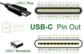
5. USB-C
USB-C is the newest USB connector standard, gaining rapid adoption in modern devices such as laptops, smartphones, and tablets. Its small, reversible design supports higher data transfer speeds and greater power delivery than earlier USB types. The USB-C pinout is more complex due to the additional functionality it offers, including support for multiple data lanes, power delivery (PD), and video output.
- VCC (Power)
- Ground (GND)
- Data+ (D+)
- Data- (D-)
- Sideband Use (SBU)
- Configuration Channel (CC)
Usage: USB-C connectors are used in a wide range of applications, including charging, data transfer, and video output. They are capable of delivering up to 100W of power, making them suitable for powering laptops and other power-hungry devices.
What Are the Key Features of USB Pinouts?
Pin Configuration for Data and Power
USB pinouts are typically configured into four main categories: power, ground, and data. Power pins provide the necessary electrical power to devices, while ground pins provide the return path for current. Data pins (D+ and D-) are responsible for transmitting and receiving data signals.
Understanding Data Transmission Modes (NRZI)
USB data transmission relies on differential signaling, where two wires (D+ and D-) carry opposing electrical signals. The data is transferred using Non-Return to Zero Inverted (NRZI) encoding, which helps improve signal integrity and reduce errors caused by electrical noise.
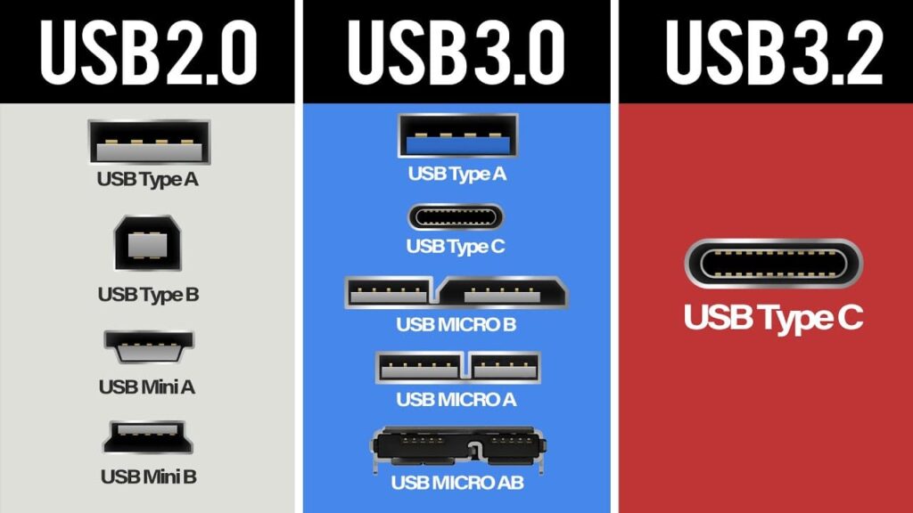
Differences Between USB 2.0, 3.0, and 3.2
- USB 2.0: Provides data transfer speeds of up to 480 Mbps. The pinout is simple, with just four pins for data and power.
- USB 3.0: Introduces additional pins to support higher data transfer rates of up to 5 Gbps. It uses the same Type-A and Type-B connectors but with additional wires for faster data transmission.
- USB 3.2: This further increases the data rate to 20 Gbps (depending on the configuration). USB 3.2 cables and connectors are backward compatible with USB 3.0 and 2.0 devices.
Why Is Understanding USB Pinouts So Important?
Troubleshooting Device Connectivity
A common issue professionals face is a USB device not being recognized by a computer. By understanding the pinout of a USB connector, you can diagnose whether the problem lies with the power supply, the data connection, or physical damage to the connector itself. Many troubleshooting steps, like checking for broken or misaligned pins, rely on a solid understanding of the pinout configuration.
USB Pinouts in Design and Customization
For hardware engineers and designers, understanding USB pinouts is crucial for creating custom cables and connectors. By modifying or designing USB systems with the correct pin configuration, professionals can ensure compatibility with a wide variety of devices, including bespoke solutions for niche applications.
Preventing Power Issues and Ensuring Efficient Data Transfer
A poor understanding of USB pinouts can lead to inefficient power delivery or data transfer, potentially damaging devices. Properly designed pinouts prevent such issues, ensuring that devices receive the correct voltage, power, and data flow. This can prevent damage, reduce power consumption, and enhance the overall efficiency of the device.
For more details, you can read this article:USB Pinout: Everything You Need to Know
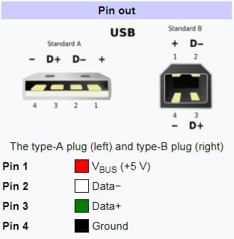
What are the 4 pins in a USB port?
USB connectors typically have four or five pins, depending on the type of USB being used. For the most common USB Type-A connector, which is typically found in host devices like computers and power adapters, there are four main pins:
- VCC (Power Pin): This pin delivers 5V DC (direct current) to the connected device, providing the power necessary for operation. It is critical to ensuring that the connected peripheral (e.g., a keyboard, mouse, or external hard drive) can draw power from the host device. In newer versions of USB (like USB 3.0 and 3.1), this pin can also support higher voltage and power delivery, but it still generally operates at 5V for most devices.
- GND (Ground Pin): The ground pin acts as the return path for the current. It completes the electrical circuit between the host and the connected device. Proper grounding ensures stable communication and helps prevent electrical interference that could disrupt data transfer.
- D+ and D- (Data Pins): These pins are used for data transfer between the host device and the peripheral. They operate using a differential signal, meaning that data is encoded as a voltage difference between the D+ and D- lines, which allows for noise reduction and more reliable data transmission.
While USB Type-A connectors generally use these four pins, other connectors, such as USB Type-B or USB-C, may include additional pins for enhanced functionality. For example, USB-C connectors can include additional pins for power delivery, alternate modes (for video output), and more advanced data transfer features.
What is D+ D- in USB?
The D+ and D- pins in a USB connector are crucial for data transmission. USB utilizes differential signaling, which means that data is transferred by sending complementary signals on these two lines. Here’s how they work:
- Differential Signaling: In USB, data is transmitted by creating a voltage difference between the D+ and D- lines. For example, when D+ is high (around 3.6V) and D- is low (around 0V), this represents a logic “1” in the data stream. Conversely, if D+ is low (0V) and D- is high (3.6V), it represents a logic “0.” This approach is known as Non-Return to Zero Inverted (NRZI) encoding. NRZI encoding helps maintain signal integrity and reduce errors in data transmission by ensuring there is always a voltage differential between the two data lines.
- Why It’s Important: The differential signal minimizes the risk of signal interference from external sources, such as electromagnetic noise, making USB a robust communication standard. This method allows for faster and more reliable data transfer, especially as USB has evolved into faster standards like USB 2.0, USB 3.0, and beyond.
In modern USB versions like USB 3.0 and USB 3.1, the data transmission also uses the D+ and D- pins for basic data transfer, but additional pins are used to increase the speed of data transfer (for instance, the introduction of SuperSpeed USB in USB 3.0).
Are USB 3.0 and 3.2 cables the same?
USB 3.0, USB 3.1, and USB 3.2 cables may look physically similar, but they differ significantly in their data transfer capabilities and internal wiring. Let’s break down the differences:
- USB 3.0: Introduced in 2008, USB 3.0 supports a maximum data transfer rate of 5Gbps (gigabits per second). It uses the same Type-A and Type-B connectors as USB 2.0 but adds additional pins for faster data transmission. These added pins enable USB 3.0 to transfer data more efficiently by using multiple data channels, which is why it offers a significant speed boost over USB 2.0 (which tops out at 480 Mbps).
- USB 3.1: USB 3.1, introduced in 2013, increased the maximum data transfer rate to 10Gbps. This version also introduced the USB-C connector, which is smaller, reversible, and supports both data transfer and power delivery. USB 3.1 also supports higher power delivery, which allows it to power larger devices such as laptops, in addition to smaller devices like smartphones.
- USB 3.2: This is the latest version in the USB 3.x family, and it can support data transfer speeds of up to 20Gbps, thanks to the addition of two lanes of data transmission. USB 3.2 cables use the USB-C connector and provide the fastest data speeds, which are ideal for high-bandwidth applications like 4K video streaming, gaming, and transferring large files rapidly.
Key Differences:
- Speed: USB 3.0 supports 5Gbps, USB 3.1 supports 10Gbps, and USB 3.2 supports up to 20Gbps.
- Cable Appearance: The physical appearance of the cables may appear identical, but the internal wiring is different. USB 3.1 and USB 3.2 require more advanced cabling to support higher speeds and power delivery. This means using a USB 3.0 cable in a USB 3.1 or USB 3.2 device will limit performance.
- Backward Compatibility: USB 3.2 devices are backward compatible with USB 3.0 and 3.1 cables, but the performance will be limited to the maximum capability of the older cables.
In summary, while USB 3.0, 3.1, and 3.2 cables look similar, the performance you get from them depends heavily on the version of USB they support and the device you’re connecting them to. For maximum speed and functionality, it’s important to use the correct cable for each device’s requirements.
What do the 4 wires in a USB cable do?
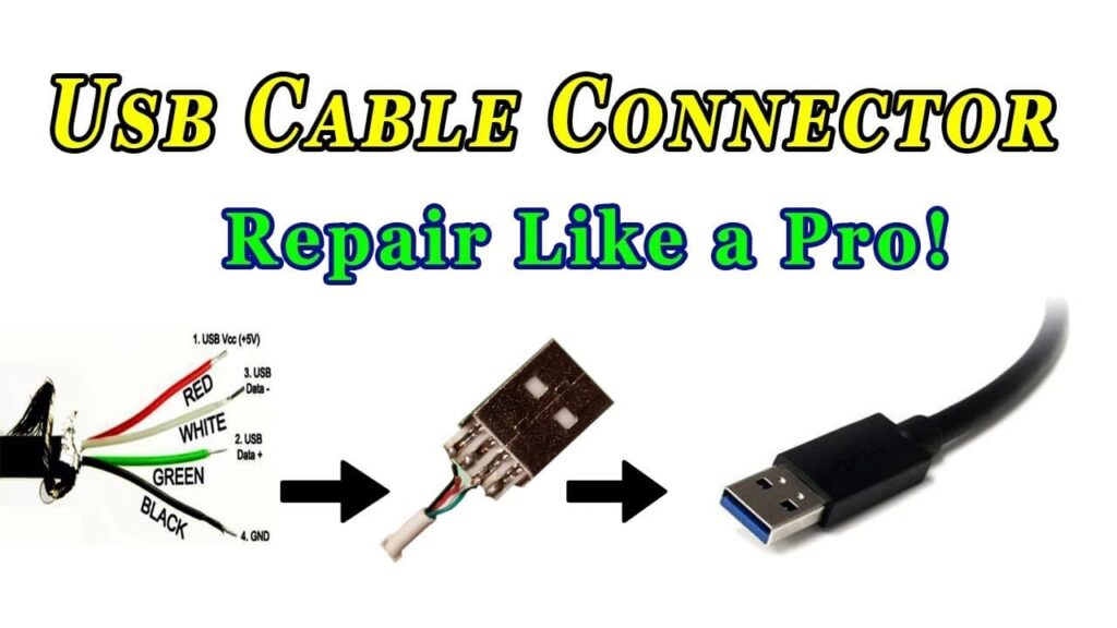
A standard USB cable typically consists of four wires, each serving a specific purpose. These wires are color-coded to help identify them easily:
- Red (VCC – Power): This wire carries the 5V DC power from the host device to the peripheral. The red wire is essential for powering USB devices, allowing them to operate without needing a separate power source. In some cases, such as with USB 3.0 and higher, the power delivered via this wire can be up to 20V or more, depending on the power delivery standard in use (USB-PD).
- Black (Ground – GND): The black wire is the ground wire, completing the electrical circuit. It provides the return path for the current supplied by the power wire. Proper grounding ensures safe operation and minimizes the risk of power surges, which could damage devices.
- Green (Data+): This wire is one of the two data transfer wires used in USB communications. It carries one of the two differential signals (D+) used to transmit data from the host device to the connected peripheral. The data transmitted through the green wire will be accompanied by the signal on the white wire, with the difference between them representing the data values.
- White (Data-): The white wire carries the second differential signal (D-) for data transmission. It works in conjunction with the green wire to enable data communication. The two wires (D+ and D-) ensure that the data is transferred reliably with reduced risk of errors caused by electrical interference.
These four wires form the basic structure of a USB cable, allowing both power delivery and data transfer between devices. Higher-speed USB versions (such as USB 3.0 and USB 3.1) may use additional wires within the cable to handle faster data transfer rates, but the basic structure remains the same for power and basic data communication.
You can see some more points from this article: USB Pinout Guide: Everything You Need to Know About USB Types and Pinouts (2024)
Limited Time Offer:
Get $100 off your order TODAY!
 Trusted by 100+ businesses worldwide No hidden fees – transparent pricing Guaranteed quality with on-time deliver
Summary
Understanding USB pinouts is essential for professionals who work with USB-based devices, whether for troubleshooting, custom design, or ensuring smooth operation. Whether dealing with the classic USB Type-A, Type-B, Micro-USB, or the newer USB-C, a detailed knowledge of pinouts allows for efficient device integration and can save time and resources.
By addressing frequently asked questions and offering insight into the workings of USB connectors, we’ve equipped you with the tools to handle common issues and understand the technical intricacies of USB technology more confidently.
Have Specific Requirements?
We’re here to help! Whether it’s a custom PCB design, assembly, or sourcing components, feel free to reach out to us directly. Our team is ready to provide tailored solutions for your project. Contact Us Today for more information.
Additional Resources:
- How to Repair Circuit Boards: A Step-by-Step Beginner’s Guide
- Capacitor on Circuit Board: A Comprehensive Guide
- What Are PCB Conformal Coatings? Types, Benefits, and Applications Explained
- SMD Size Codes Explained: A Complete Guide to Understanding Surface-Mount Component Dimensions
- AC vs DC: Key Differences, Applications, and Advantages in Modern Electronics
Request for Quote
RECENT POSTS
IC Boards Explained: Applications, Layout Tips, and Assembly Services
Discover what IC boards are, how they’re used in modern electronics, and how to design
HDI PCB vs Multilayer PCB: How to Choose the Right One for Cost, Signal Integrity & Manufacturing
HDI PCB vs multilayer PCB explained from a manufacturing and assembly perspective. Learn how cost,
RELATED POSTS

Leading PCBA Manufacturer
✅ Assemble 20 PCBAS for $0 ✅ Get $100 OFF – Risk-Free Trial!
✅ 100+ Satisfied Customers
✅ Ensured Quality & On-Time Delivery
✅ Free Trial, No Commitments!