Quick Leads
What is GND in a Circuit? Understanding Its Role and Importance in Electronics
When you’re working with electrical circuits, GND (Ground) is one of the most critical and foundational elements. Whether you’re designing a PCB or troubleshooting an existing system, understanding what GND is and how it functions will ensure your circuit operates safely and effectively. Let’s dive into the details.
What is GND in a Circuit?
GND stands for Ground, a key concept in electrical circuits. Ground is essentially a reference point of voltage for the system, and it serves as the return path for electrical current. When current flows through a circuit, it returns to the power source through the GND path, completing the electrical circuit. GND provides a stable reference for measuring voltage and ensures the circuit operates safely, without fluctuations or electrical hazards.
In most circuits, the GND pin or wire is connected to the negative terminal of a power supply or battery, but its role goes beyond just completing the circuit. It helps stabilize the voltage and protects against electrical surges.

Functions of GND in a Circuit
GND has several important functions in electrical and electronic circuits:
- Completes the Circuit:
- GND is the return path for current, enabling the current to flow from the positive side of the power supply, through the circuit components, and back to the power source.
- Voltage Reference:
- GND acts as the zero-voltage reference point for all components in the circuit. Without a common reference, voltage measurements would be inconsistent, leading to faulty operation.
- Safety:
- Proper grounding ensures that excess current or fault currents can safely dissipate, minimizing the risk of electrical shock or fire.
- Prevents Ground Loops:
- GND is important for ensuring there are no ground loops—unwanted voltage differences between various ground points in a circuit, which can lead to noise or interference.
- Signal Integrity:
- In sensitive electronic circuits, GND helps maintain signal integrity by minimizing electrical noise or interference from other signals or the environment.
Types of GND in Electrical and Electronic Circuits
There are different types of GND, each serving a unique function within a circuit:
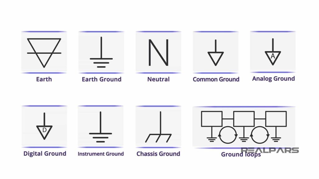
- Chassis Ground (Frame Ground):
- A physical connection between the circuit and the metal enclosure of an electronic device, providing safety by dissipating any stray electrical current.
- Signal Ground:
- Used in analog circuits and mixed-signal systems. It provides a reference for signal voltages, ensuring that all components in the circuit maintain consistent signal levels.
- Earth Ground:
- Earth ground connects the system to the physical Earth, providing a safe path for excess current, particularly in high-voltage systems.
- Floating Ground:
- Isolated from the power supply or external reference point, often used in battery-operated devices or instruments that need electrical isolation.
- Digital Ground:
- A reference ground for digital components, ensuring clean, reliable digital signals without interference from analog components.
What Does the GND Do in a Circuit?
GND serves several critical functions in a circuit, including:
- Completing the Current Path: GND allows electrical current to flow from the power supply, through the components, and back to the source. Without GND, the circuit would be open and current would not flow.
- Voltage Reference: All components in a circuit need a common reference point. GND is typically used as the zero-voltage reference, and voltage measurements are made relative to GND.
- Prevents Electrical Hazards: GND serves as a protective path, ensuring that excess currents due to faults or power surges can safely flow to Earth or to the power source.
- Minimizes Noise: Proper grounding minimizes electromagnetic interference (EMI), which can cause noise and signal degradation in sensitive circuits, especially in analog and mixed-signal systems.
What Does a GND Wire Do?
A GND wire connects the circuit’s ground reference point to various components in the system. The GND wire ensures that all components share a common reference voltage, which is essential for their proper operation. Specifically, it:- Provides a return path for current, completing the circuit.
- Helps maintain voltage stability by serving as the reference for voltage levels.
- Ensures safety by directing excess current to a safe path.
What Does GND Mean on a Breaker?
On a breaker, GND typically refers to the grounding connection of the electrical circuit. In electrical breakers and distribution systems, the GND connection ensures that any excess current or faults are safely discharged to the ground, protecting both the circuit and users from potential electrical hazards. The GND connection on a breaker is linked to the Earth, which acts as the safeguard to prevent electrical shocks or fires. Proper grounding at the breaker level is essential for the safety and reliability of electrical installations.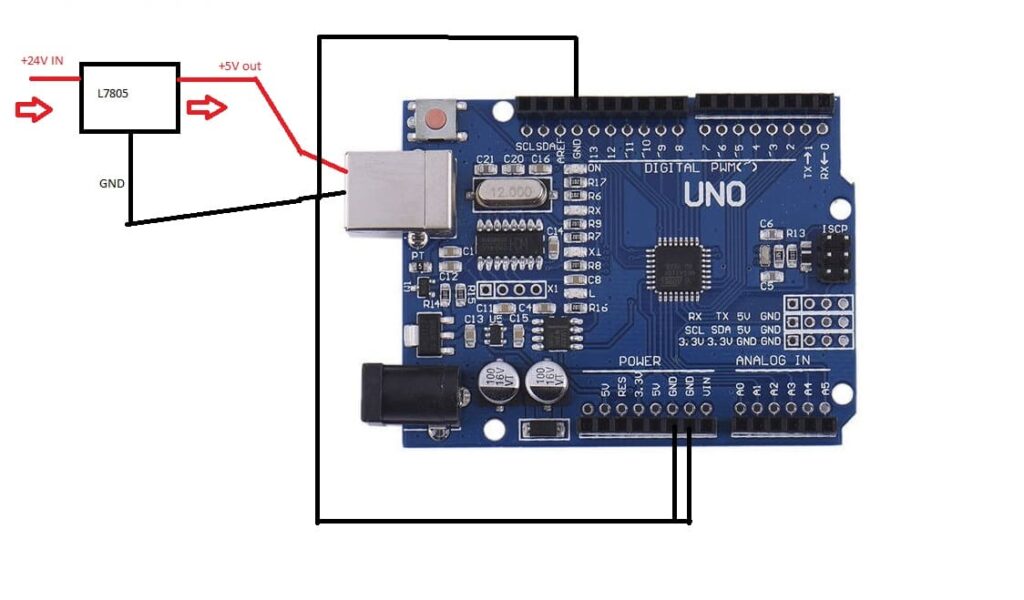
Where to Connect GND in a Circuit?
Knowing where to connect GND in a circuit is essential for ensuring that the circuit functions correctly, safely, and without issues like noise or instability. Below are the key areas where GND should be connected in different types of circuits:
1. To the Negative Terminal of the Power Supply
In most circuits, GND is connected to the negative terminal of the power supply or battery. This connection creates the return path for electrical current:
- Current Flow: The current flows from the positive terminal of the power source through the circuit components and eventually returns to the power supply’s negative terminal via the GND.
- Closed Loop: This creates a closed loop, allowing the current to continuously flow through the system, ensuring the circuit works as intended. If GND is not connected properly to the negative terminal, the circuit will fail to complete, and no current will flow.
2. Common Ground Point for Components
For all the components in the circuit, whether they are sensors, microcontrollers, LEDs, motors, or other electronic parts, it’s essential that they all share a common ground:
- Voltage Reference: This ensures that all components are referencing the same voltage potential, which is crucial for proper operation and communication. For instance, if a microcontroller (like an Arduino) is interfacing with a sensor, the GND pin of the microcontroller must be connected to the GND of the sensor. If these devices don’t share a common ground, signals may not be correctly interpreted, leading to malfunction.
3. Connection to Earth Ground for Safety
In many high-power systems or larger installations, GND is connected to Earth ground for safety reasons:
- Electrical Faults: If there is a short circuit or fault in the system, the Earth ground provides a safe path for the excess current to flow into the Earth, rather than remaining within the system, which could lead to electrical shock or fires.
- Protection: This connection is particularly critical for industrial machines, household appliances, or any systems that operate on AC mains power where high voltages are involved.
4. PCB Grounding
When designing a Printed Circuit Board (PCB), proper grounding becomes even more important for ensuring efficient operation:
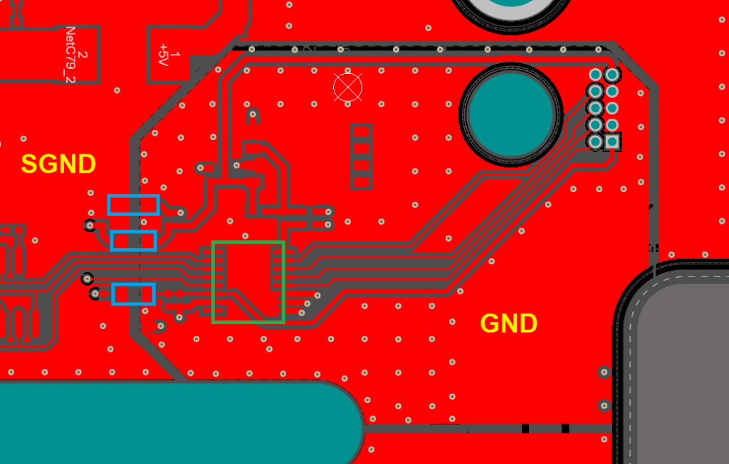
- Ground Plane: Most modern PCBs use a ground plane, a large, continuous area of copper on the PCB that serves as the reference for all components and signals. This plane minimizes resistance and electrical noise, providing a stable voltage reference for the entire circuit. Ideally, the ground plane should be as continuous and unbroken as possible to minimize the resistance path for current.
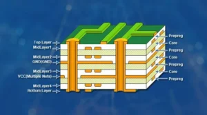
- Multiple Ground Layers: In complex PCBs (especially multi-layer designs), multiple ground layers may be used to reduce noise and improve the performance of the system. The ground layers can be placed between signal layers to shield sensitive components from electromagnetic interference (EMI).
5. Multiple Grounds for Complex Systems
In more complex circuits, like mixed-signal or high-power systems, you may have different types of grounds, and it’s crucial to connect them correctly:
- Signal Ground: Separate from the power ground and often used in circuits where analog and digital signals need to be isolated.
- Power Ground: This ground connects the power supply and high-current components.
- Chassis Ground: A dedicated ground that connects the physical housing or frame of the system to the common ground point.
- Single-Point Grounding: It’s essential to connect all these different types of grounds at a single point (usually at the power supply or earth ground) to prevent ground loops that can cause electrical noise or system instability.
In mixed-signal systems, it’s common to isolate the digital ground (DGND) from the analog ground (AGND) to ensure that digital noise doesn’t interfere with the sensitive analog signals.
What is GND in a Circuit Board?
On a Printed Circuit Board (PCB), GND plays a critical role in ensuring that all signals and voltages are referenced correctly for the circuit to work as intended. Here’s a deeper dive into how GND functions within the PCB layout:
1. Ground Plane
A ground plane is a large area of copper that acts as a common reference for all components and signals on the board:
- Minimizes Noise: The ground plane helps minimize resistance and electrical noise, providing a stable voltage reference for the entire system.
- EMI Reduction: A solid ground plane reduces electromagnetic interference (EMI), which can affect the circuit’s performance. A continuous, unbroken ground plane provides the lowest possible resistance and is crucial for signal integrity.
Ideally, the ground plane should be as continuous and unbroken as possible, with minimal cuts or vias. These interruptions can introduce noise and increase resistance, which can affect the overall performance.
2. GND Traces
In addition to the ground plane, GND traces are used to connect individual components to the ground:
- Current Handling: The width and thickness of the GND traces must be designed to handle the current that passes through them without excessive voltage drop or overheating. If the traces are too thin, they may cause the system to overheat or even damage components.
- Thick Traces and Copper Pours: In high-power designs, where more current is involved, designers may use thick traces or copper pours to ensure that the ground connection can handle higher currents without overheating or causing voltage drops.
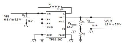
3. Decoupling Capacitors
Decoupling capacitors are often used near the power pins of sensitive components (like microcontrollers or operational amplifiers). These capacitors:
- Filter Noise: Help to smooth out voltage spikes or noise that can interfere with the operation of the components.
- Stable Voltage: Connect the power supply pin to GND, ensuring that the voltage delivered to sensitive components remains stable and free of fluctuations or noise.
4. Multiple Ground Layers in Multi-Layer PCBs
In multi-layer PCBs, multiple ground layers can be used to minimize noise and ensure signal integrity:
- Lower Impedance: The ground layers provide a low impedance return path for current, which helps to reduce noise between power and signal lines. These layers can be strategically placed between signal layers to shield sensitive components and traces from EMI.
- Separation of Power and Signal Grounds: In complex systems, it is important to separate power grounds and signal grounds. This can be achieved through multi-layer PCBs where different ground layers are dedicated to power and signal lines. By doing so, you reduce the chances of high-current power lines affecting the low-power signals.
5. Connecting Components to GND
Each component on the PCB—whether it is an IC, resistor, capacitor, or any other part—has a GND pin that is typically connected to the ground plane or ground traces:
- Uniform Potential: This ensures that all components on the board are referencing the same voltage potential, which is essential for proper circuit operation.
- Minimizing Noise and Interference: Ground connections should be as short and direct as possible to reduce inductance and resistance. Excessive length can lead to noise, particularly in high-frequency circuits.
6. Design Considerations
Proper grounding is crucial in PCB design for:
- Electromagnetic Interference (EMI): Poor grounding can lead to EMI problems, which can affect circuit performance, especially in analog circuits or high-speed digital circuits.
- Signal Integrity: Poorly implemented ground connections can cause ground loops, crosstalk, and oscillations, all of which can degrade performance or cause malfunctioning.
- Thermal Stability: Adequate grounding also helps with thermal stability by ensuring that heat generated by current flow can dissipate properly.
Is GND Positive or Negative?
GND is typically considered negative in most circuits. It serves as the return path for current, while the positive terminal of the power supply provides the high potential from which current flows through the circuit. In certain situations, however, GND could also be referenced as zero potential rather than positive or negative.
In AC systems, neutral is sometimes referred to as ground, but the terminology varies based on context.
What is GND in a Circuit Board?
On a circuit board, GND serves as the reference point for all signals and power. Ground traces or planes on the board ensure that all components share a common voltage reference, crucial for circuit integrity. In PCB design:
- GND plane is often used to minimize noise and maintain stable signals.
- GND traces connect individual components to the ground plane.
- The GND layer can help shield sensitive components from electromagnetic interference (EMI).
It’s crucial to design GND connections carefully, especially in high-speed or complex circuits, to avoid ground loops or signal degradation.
What is GND in Arduino?
In Arduino, GND is the ground pin that is connected to the common reference point of the circuit. All components that communicate with the Arduino (such as sensors, motors, or LEDs) must be connected to the GND pin to ensure that they share the same voltage reference. The Arduino GND pin typically connects to the negative terminal of the power supply, just like any standard GND connection.
What is GND in Tesla Circuits?
In Tesla circuits or electrical systems, GND is the reference point for all voltages and acts as a return path for the current. Tesla’s electrical systems may include high-voltage power supplies, so proper grounding is critical for both safety and performance. GND helps prevent electrical hazards such as shocks or fires by safely directing excess current to Earth or a dedicated safe location.
Frequently Asked Questions
- R for resistors
- C for capacitors
- L for inductors
- U for integrated circuits (ICs)
- D for diodes
- T for transformers
- TP for test points
Components are identified using printed labels (e.g., “R” for resistors), color codes (e.g., resistor bands), and circuit symbols. Reference designators like R1 or C3 further specify the exact component on the board.
IPC-7351 ensures proper pad design for components, while IEC 61360 standardizes component names for clear communication. Following these standards improves reliability and reduces manufacturing errors.
Professionals use tools like multimeters and reference designators (e.g., R5, C8) to locate and test faulty components. This method ensures accurate repairs and minimal downtime.
Limited Time Offer:
Get $100 off your order TODAY!
 Trusted by 100+ businesses worldwide No hidden fees – transparent pricing Guaranteed quality with on-time deliver
Summary
Understanding GND and its role in electronic circuits is essential for anyone working with electrical systems, from PCB designers to engineers sourcing PCB assembly services. GND acts as the reference point for all voltage measurements, completes the current path, ensures the circuit operates safely, and helps maintain signal integrity. Whether you’re working on a basic circuit or designing a complex PCB, knowing where and how to properly implement GND will ensure the reliability and safety of your system.
If you’re looking for professional PCB assembly services, make sure to choose a provider who understands the intricacies of grounding and can deliver high-quality, reliable designs.
Have Specific Requirements?
We’re here to help! Whether it’s a custom PCB design, assembly, or sourcing components, feel free to reach out to us directly. Our team is ready to provide tailored solutions for your project. Contact Us Today for more information.
Additional Resources:
- How to Repair Circuit Boards: A Step-by-Step Beginner’s Guide
- Capacitor on Circuit Board: A Comprehensive Guide
- What Are PCB Conformal Coatings? Types, Benefits, and Applications Explained
- SMD Size Codes Explained: A Complete Guide to Understanding Surface-Mount Component Dimensions
- AC vs DC: Key Differences, Applications, and Advantages in Modern Electronics
Request for Quote
RECENT POSTS
Multilayer PCB Signal Integrity: Expert Design Rules for Noise-Free Performance
Discover expert multilayer PCB signal integrity design rules and turnkey assembly solutions to ensure noise-free,
What is HDI PCB? | Ultimate Guide to Benefits, Structure, and Real-World Applications
Discover what HDI PCB is, how it works, and why our turnkey HDI PCB assembly
RELATED POSTS


Leading PCBA Manufacturer
✅ Assemble 20 PCBAS for $0 ✅ Get $100 OFF – Risk-Free Trial!
✅ 100+ Satisfied Customers
✅ Ensured Quality & On-Time Delivery
✅ Free Trial, No Commitments!