Quick Leads
How to Wire Potentiometers for IoT Devices: A Step-by-Step Guide to Scaling Your Smart Products
Potentiometers are key components in electronics, widely used in various applications such as volume control, light dimming, and temperature regulation. Whether you’re designing a smart thermostat, IoT sensor, or another cutting-edge device, understanding how to wire potentiometers correctly is essential. In this guide, I’ll walk you through the process of wiring potentiometers, focusing on real-world applications for IoT products like smart thermostatic radiator valves, and how to scale these designs for high-volume production. If you’re building products at scale, these tips will help ensure that your potentiometer wiring is both efficient and reliable.
To wire a potentiometer, connect one outer terminal to ground, the other outer terminal to power (typically 3 to 5 volts), and the middle terminal (wiper) to the analog input pin of your microcontroller or sensor. This configuration allows you to vary the voltage, making potentiometers an ideal choice for precise control in IoT products like thermostats, lighting, and other smart devices.
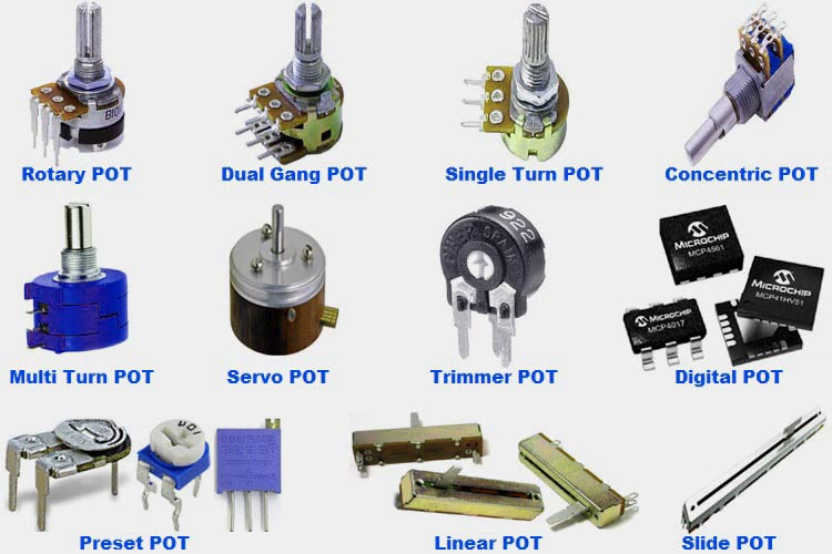
Now that we’ve covered the basics of potentiometer wiring, let’s dive deeper into different types of potentiometers, their applications, and how to optimize your wiring for high-volume production in products like smart thermostats and IoT devices. Whether you’re a maker or an engineer, these steps will guide you through the process.
How Should a Potentiometer Be Wired?
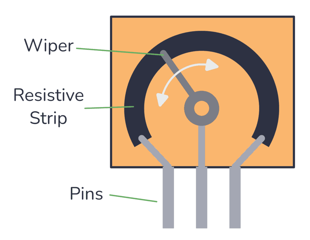
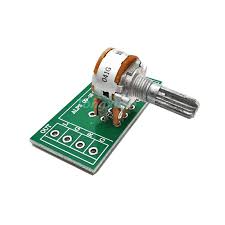
Wiring a potentiometer is pretty straightforward, but it’s important to do it correctly to ensure reliable performance. A potentiometer has three terminals:
- Outer Terminals: These are typically the terminals connected to ground and power (e.g., 3.3V or 5V).
- Wiper Terminal: The middle terminal, which adjusts as you turn the knob or slide the control. It’s connected to the analog input pin on your microcontroller or sensor, where the voltage is read.
The voltage across the potentiometer changes as the wiper moves, making it a great tool for applications like volume control, sensor calibration, or adjusting temperature in smart devices.
- Tutorial: Using a Potentiometer
- Description: This tutorial provides an in-depth look at wiring potentiometers for various applications, ideal for IoT projects. It offers hands-on guidance and is relevant for users seeking detailed knowledge on potentiometer setups.
What Are the 3 Terminals on a Potentiometer?
A potentiometer typically has three terminals:
- Wiper Terminal (middle): This terminal is where the voltage is read, and it changes based on the position of the adjustment mechanism (knob or slider).
- First Outer Terminal: This terminal is typically connected to power (3.3V or 5V).
- Second Outer Terminal: This is connected to ground (0V).
As you adjust the potentiometer, the resistance between the wiper terminal and each outer terminal changes, allowing you to control the voltage at the wiper. This is the key to making IoT devices respond to user inputs like volume levels or temperature adjustments.
Does a Potentiometer Need to Be Grounded?
The short answer is yes: grounding is important when using a potentiometer in most electronic circuits. While a potentiometer itself doesn’t need to be “grounded” to work, the outer terminals need to be connected to ground and power for the potentiometer to operate correctly.
Without a stable ground connection, you might experience issues like fluctuating voltage or unstable sensor readings. Proper grounding ensures that your IoT products, such as smart thermostats and lighting controls, function reliably and provide accurate feedback.
- How to Wire Potentiometers in Different Configurations
- Description: This guide covers the wiring configurations of potentiometers in detail, particularly useful for engineers working with IoT devices and looking for reliable wiring practices.
Can You Wire a Potentiometer Backwards?
Yes, you can wire a potentiometer backward, though it’s not recommended for most situations. Reversing the outer terminals will make the potentiometer behave in the opposite way, but the adjustment will still function.
If you’re designing a user interface where you want the potentiometer to behave differently (for example, to adjust a parameter in the opposite direction), reversing the terminals may be useful. For most applications, like temperature control or volume adjustment, however, the standard wiring configuration is preferred for consistency and ease of use.
- Basics of Potentiometers with Arduino
- Description: This official Arduino documentation explains how potentiometers are used in electronic circuits, especially in DIY IoT projects. Great for readers integrating potentiometers with Arduino for IoT applications.
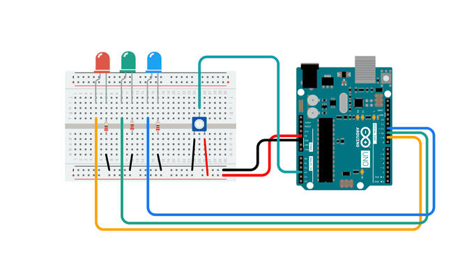
Potentiometer Wiring for Arduino Projects
Potentiometers are commonly used in Arduino projects for applications like analog input sensing or user-controlled adjustments. If you’re using a potentiometer with an Arduino board, wiring it is pretty simple:
- Connect one outer terminal to 5V (or 3.3V if using a low-power Arduino board).
- Connect the other outer terminal to ground.
- Attach the wiper terminal to an analog input pin on your Arduino (e.g., A0).
You can then use the analogRead() function in your Arduino code to read the potentiometer’s voltage, which will range from 0 (ground) to 1023 (maximum voltage). This is especially useful in applications like robotics, sensor calibration, and controlling smart devices.
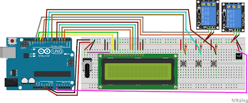
Potentiometer Wiring Diagrams
For those who prefer visuals, here are some examples of common potentiometer wiring diagrams:
Basic 3-Pin Potentiometer Wiring: This is the most straightforward setup, with one terminal connected to power, one to ground, and the wiper connected to an input pin.
Example diagram:
- Power → Outer Terminal 1
- Ground → Outer Terminal 2
- Wiper → Analog Input Pin
4-Pin Potentiometer Wiring: A more complex configuration, used in multi-channel or voltage divider circuits, where an additional terminal is added for more control.
6-Pin Potentiometer Wiring: Used in precision systems and multi-axis controls, like joystick devices or advanced volume control circuits.
Each diagram provides a clear representation of how to wire the potentiometer for different needs, from simple adjustments to complex feedback systems.
- Electronic Potentiometer Wiring Guide
- Description: A detailed guide on wiring potentiometers in various applications. It covers both theoretical and practical aspects of potentiometer wiring, helping engineers and technicians design IoT devices effectively.
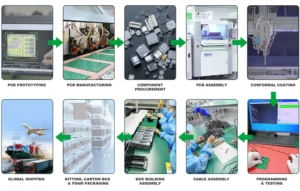
Potentiometer Wiring for High-Volume Manufacturing
When designing products for mass production, like IoT devices or smart thermostats, it’s crucial to focus on scalability and reliability. Wiring potentiometers for high-volume production introduces some challenges, but with the right approach, you can ensure your products are both functional and durable.
Key considerations for high-volume potentiometer wiring:
- Consistency: In mass production, each unit needs to have identical wiring to maintain consistent performance across all devices. Ensuring every potentiometer is wired the same way guarantees that each device will function as expected.
- Durability: Potentiometers used in consumer devices like thermostats and smart home products need to withstand frequent use. Choose potentiometers that are built for longevity and can endure multiple cycles of adjustment without failure.
- Integration: Potentiometers must work seamlessly with other sensors and electronics in your device. Whether you’re controlling a thermostat, smart lighting, or IoT sensors, proper wiring is critical for integrating the potentiometer into the larger system.
By working with a skilled PCB assembly service that specializes in IoT product development, you can streamline the manufacturing process and scale your product production without compromising quality.
FAQs
Potentiometers offer precision voltage control, making them ideal for sensor calibration and user-adjustable controls in IoT devices. Whether it's adjusting temperature or lighting, they allow for smooth, reliable changes, enhancing the user experience.
Consider factors like the resistance value, taper type (linear or logarithmic), and the mechanical form (rotary or slide). For IoT devices, compact size and high durability are key for reliable performance.
Potentiometers are generally designed for low to moderate power applications. For high-power tasks, you may need to look into variable resistors or digital potentiometers that are specifically rated for higher power handling.
In outdoor applications, ensure your potentiometer is weather-resistant and sealed against dust and moisture. Encapsulating the potentiometer in a protective housing or using IP-rated components can help protect it in harsh environments.
Limited Time Offer:
Get $100 off your order TODAY!
 Trusted by 100+ businesses worldwide No hidden fees – transparent pricing Guaranteed quality with on-time deliver
Summary
Wiring a potentiometer is a straightforward but essential task in the design of IoT devices like smart thermostats, lighting controls, and more. Understanding the wiring process and the different types of potentiometers will ensure that your projects are both efficient and scalable. Whether you’re building products for the consumer market or industrial use, getting the wiring right is crucial. Ready to get started? Contact us today to discuss how our PCB assembly services can help take your product from concept to high-volume production, ensuring reliability and precision at every stage.
Next Steps
- Explore more potentiometer configurations for your specific needs.
- Learn how to integrate potentiometer feedback into IoT products for better user interaction.
- Connect with our team for expert PCB assembly services tailored to your manufacturing needs.
Have Specific Requirements?
We’re here to help! Whether it’s a custom PCB design, assembly, or sourcing components, feel free to reach out to us directly. Our team is ready to provide tailored solutions for your project. Contact Us Today for more information.
Additional Resources:
- How to Repair Circuit Boards: A Step-by-Step Beginner’s Guide
- Capacitor on Circuit Board: A Comprehensive Guide
- What Are PCB Conformal Coatings? Types, Benefits, and Applications Explained
- SMD Size Codes Explained: A Complete Guide to Understanding Surface-Mount Component Dimensions
- AC vs DC: Key Differences, Applications, and Advantages in Modern Electronics
Request for Quote
RECENT POSTS
IC Boards Explained: Applications, Layout Tips, and Assembly Services
Discover what IC boards are, how they’re used in modern electronics, and how to design

HDI PCB vs Multilayer PCB: How to Choose the Right One for Cost, Signal Integrity & Manufacturing
HDI PCB vs multilayer PCB explained from a manufacturing and assembly perspective. Learn how cost,
RELATED POSTS

Leading PCBA Manufacturer
✅ Assemble 20 PCBAS for $0 ✅ Get $100 OFF – Risk-Free Trial!
✅ 100+ Satisfied Customers
✅ Ensured Quality & On-Time Delivery
✅ Free Trial, No Commitments!