Quick Leads-PCBA
 Looking for full-service PCB Assembly?
Turnkey solutions from PCB manufacturing to testing.
sales@unitcircuits.com
🟢Why Talk About PCB Transformers in 2026?
If you’ve ever tried to design a compact power supply or a control circuit for industrial gear, you know how much hinges on getting your transformer right. A lot of people still think transformers belong in big metal boxes or old-school wall adapters — but in the world of modern PCB design, they’ve gone smaller, smarter, and more integrated.
So whether you’re figuring out how to design a PCB transformer circuit, sourcing SMT PCB transformers, or just trying to wrap your head around coil winding on a 4-layer board, this guide is here to help.
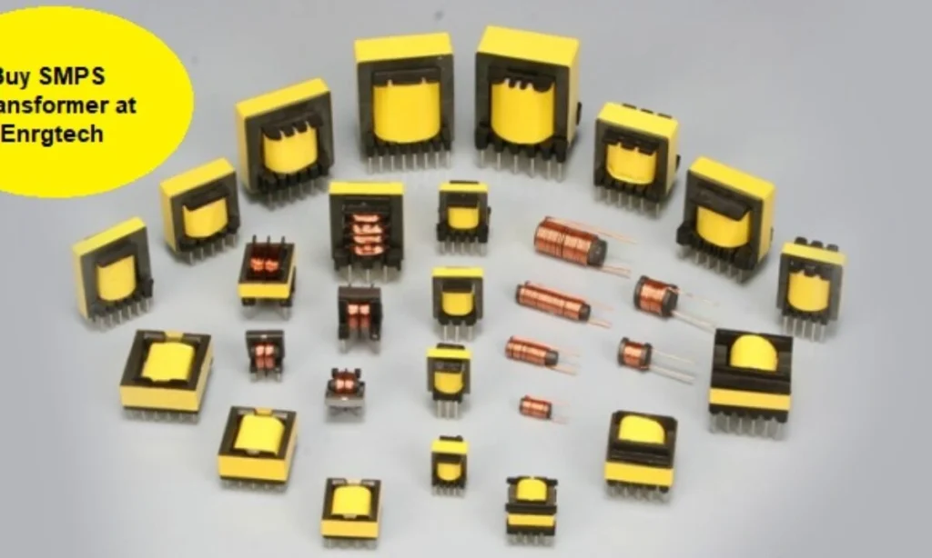
🟡What Is a PCB Transformer and Why Is It Different?
Let’s start with the basics: What is a PCB transformer? In short, it’s a compact transformer that’s designed to be mounted directly onto a PCB — either as a through-hole component or in surface-mount form.
Just like traditional transformers, they rely on electromagnetic induction to transfer power between windings. But in PCB form, they’re often optimized for:
High-frequency switching
Low-profile integration
Automated SMT or hybrid assembly
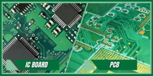
And while they still do classic transformer jobs like voltage conversion, circuit isolation, and relay control, they’re just a lot more compact.For a clearer understanding of how transformers fit into the bigger picture of board design and assembly, check out our guide on what PCBA is and how it differs from standard PCBs.
🔍 PCB Transformer vs. Traditional Transformer: What’s the Real Difference?
Here’s how they compare in real-world terms:
| Feature | PCB Transformer | Traditional Transformer |
|---|---|---|
| Mounting | Through-hole or SMT on PCB | Chassis-mounted, wired separately |
| Size | Compact, fits standard PCB footprints | Often bulky and external |
| Application | SMPS, IoT, relay control, AC-DC boards | Audio amps, high-voltage isolation, heavy power |
| Assembly | Automated pick-and-place compatible | Manual placement, enclosure mounting |
| Cooling & Clearance | Relies on PCB layout and copper planes | External heatsinks or passive cooling |
So no — PCB transformers aren’t less capable. They’re just different. They’re designed for speed, automation, and space efficiency.
🔹How Does a PCB Transformer Work? (Simple, But Critical)
You’ve got a primary winding, a magnetic core, and a secondary winding. When AC voltage is applied to the primary, it creates a magnetic field in the core. This field crosses over to the secondary winding, where it generates a different voltage — depending on the turns ratio.
It’s classic electromagnetic induction, optimized for:
Galvanic isolation (especially in PCB power transformer designs)
Step-down or step-up voltage handling
Signal or logic isolation in mixed-voltage boards
🧠 Quick Terms to Know:
Ferrite core transformer → Lightweight, ideal for high-frequency use
Flyback transformer → Stores energy during the switch-on phase and transfers it during off-time; used in SMPS
Coil winding → The number of turns in the primary vs. secondary controls voltage transformation
This is the engine behind PCB transformers for AC to DC conversion, relay control with PCB transformer, and even noise filtering in IoT sensors. It’s classic electromagnetic induction, optimized for isolation and voltage handling. Learn more about transformer basics here.
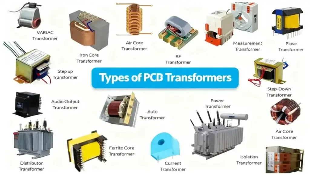
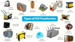
Types of PCB Transformers: What to Use and When
Knowing your transformer options helps you avoid overkill or underperformance. Here are the common types used in modern PCB layouts.
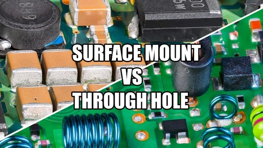
1. Through-Hole PCB Transformers
These are your classic big-bodied transformers with long leads. They’re:
Easy to solder manually
Great for higher current applications
More rugged than SMT options
Use them when you’re building control boards, AC-DC converters, or relay logic circuits that deal with higher voltages or need better heat dissipation.
2. SMT (Surface Mount) PCB Transformers
These are low-profile transformers made for high-speed automated assembly. Ideal for:
Compact layouts
Low-voltage applications
IoT or wearable PCB designs
They’re often used in SMT relay control circuits, signal isolation, or power supply feedback loops.
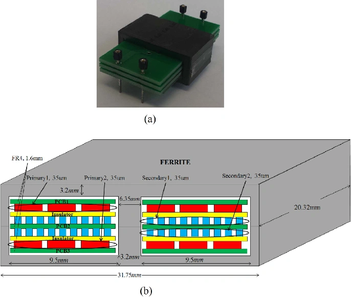
3. Planar Transformers
These look futuristic because they are. Planar transformers:
Use flat copper windings on PCB layers
Are extremely compact
Support high-frequency switching
They’re found in high-density SMPS, power modules, and other space-constrained PCB assemblies. If you’re combining SMT and THT components like PCB transformers on one board, don’t miss our practical guide on hybrid PCB assembly and overcoming layout challenges. Planar transformers are compact and ideal for high-frequency switching. Here’s a deeper look at how they work.
4. Isolation Transformers vs. Signal Transformers
Let’s make that distinction:
| Transformer Type | Key Function | Best Use Case |
|---|---|---|
| Isolation Transformer | Keeps sections of a circuit electrically separate | Protecting MCUs, AC line isolation |
| Signal Transformer | Passes or filters analog/digital signals | Audio, data lines, CAN bus |
Unit Circuits: Leading PCBA Manufacturer
 ISO-certified & 8+ years of PCBA Low MOQ & Fast Turnaround Prototype & Mass production
Limited Time Offer:
Get $100 off your order TODAY!
sales@unitcircuits.com
🔹Design Tips: How to Integrate Transformers into Your PCB
If you’re working on PCB transformer circuit design, here’s where most problems start: the layout. Transformer integration isn’t just about dropping the part on your schematic.
Here’s what you really need to think about.
1. Get the Right Footprint
A mismatched footprint will kill your production run. Double-check:
Pad size and spacing
Mounting hole alignment (if needed)
Creepage and clearance distances — especially if dealing with AC mains
💡 Tip: Always follow the transformer footprint in PCB layout datasheet. Or ask your assembly house (like us) to verify it during DFM review.
2. Heat Management & EMI
Transformers generate heat — especially in high-frequency or high-load designs. Plan for:
Copper pours under the transformer
Vias to spread heat into inner layers
Clearance from sensitive signal traces
For EMI, consider:
Ferrite beads on the input/output lines
Physical spacing from analog sections
Shielded cans (if your design allows it)
3. Do’s and Don’ts of Transformer Circuit Design
✅ DO:
Use wide, short traces for primary/secondary paths
Isolate transformer zones from logic ICs
Keep differential signal lines away from magnetic components
❌ DON’T:
Overlap AC and logic planes without insulation
Ignore voltage rating between windings
Assume “any transformer will do”
🔹Common Pain Points (and What We Do About Them)
We work with engineers every day on custom PCB transformer manufacturing, and some issues come up again and again. Here’s what you might run into — and how we handle it.
❌ Pain Point 1: Long Lead Times for Custom Transformers
You order a PCB transformer with specific voltage isolation specs.
The vendor goes quiet.
You’re waiting 5 weeks for samples.
✅ Our Fix: We work with verified transformer manufacturers who pre-qualify parts for low-profile, high-frequency, or isolation-critical applications. Plus, we review transformer specs before production starts.
❌ Pain Point 2: Transformer Doesn’t Fit the Board
This one hurts. You designed for a low-profile SMT transformer, but what shows up is 2 mm taller and overlaps a connector.
✅ Our Fix: We check transformer height, pin pitch, and thermal profile during the DFM (Design for Manufacturing) stage — before production starts.
❌ Pain Point 3: Not All Assembly Houses Handle THT Transformers Well
Through-hole transformers often require:
Wave soldering
Manual inspection
Ferrite core handling
✅ Our Fix: We run hybrid SMT + THT lines with manual transformer handling, ensuring solder quality and core safety. We also visually inspect each transformer mount point. To ensure your PCB transformer circuits function correctly after assembly, review our top 5 PCBA testing methods to guarantee quality and isolation performance.
🔹Real-World Use Cases for PCB Transformers
These aren’t just theory. Here’s where we’ve seen PCB transformers in action — and how they solve real design problems.
⚙️ Use Case 1: Powering SMPS Boards
PCB transformer for SMPS use is almost universal.
Flyback transformers store energy and regulate output
Planar transformers reduce EMI and footprint
They isolate the low-voltage logic from high-voltage AC input
This is essential for wall adapters, LED drivers, and energy-efficient modules.”They isolate the low-voltage logic from high-voltage AC input — a key function in isolated power supply design. This guide explains the full process.
⚙️ Use Case 2: Relay Control Boards
A lot of relay-based automation circuits rely on PCB transformers to:
Power the relay coil from AC
Step down 220V mains to 12V/5V
Isolate MCU circuits from high-current switching
If you’re designing an industrial relay control system, a compact transformer is a must.
⚙️ Use Case 3: Smart IoT & Embedded Modules
Tiny, silent transformers? Yes, they exist. In IoT:
Transformers enable safe power conversion in smart plugs, energy meters
Provide voltage isolation in mixed-signal PCBs
Fit into low-profile SMT transformer footprints on a 4-layer board
FAQs
1. What are PCBs in a transformer?
In transformer design, PCBs (Printed Circuit Boards) are often used to mount compact transformers directly onto the board. A PCB in this context serves as the platform that supports electrical connections and component placement. PCB-mounted transformers are ideal for space-saving, automated assembly, and high-frequency switching applications. They're commonly used in IoT devices, power modules, and relay control boards.
2. What is the use of transformers in PCB?
Transformers in PCB circuits are used for voltage conversion, galvanic isolation, and signal conditioning. Whether in SMPS power supplies, embedded IoT systems, or relay driver circuits, these transformers ensure electrical safety and performance. They allow different parts of a system to communicate or share power without direct electrical contact — which is critical in mixed-voltage environments.
3. What are the 4 types of transformers commonly used in PCBs?
The four most common PCB transformer types are:
Through-hole transformers – for high-power, easy-to-solder applications.
SMT transformers – compact and ideal for automated assembly.
Planar transformers – ultra-flat for high-density power supplies.
Signal transformers – for filtering or transferring analog/digital signals.
Choosing the right type depends on voltage, frequency, and space constraints.
4. How to identify PCB transformers on a circuit board?
To identify a PCB transformer, look for components with multiple windings or wire coils, often wrapped around a ferrite core. They may be labeled as T1, TR1, or similar. Surface-mount versions are usually compact, block-shaped, while through-hole types are larger with visible pins. Use datasheets or silkscreen labels to verify specifications like input/output voltage, turns ratio, and frequency rating.
Have Specific Requirements?
Looking for high-precision PCB assembly for your products? Our team specializes in delivering top-tier assembly services, ensuring your devices perform flawlessly in any environment. Contact us today for a free consultation on how we can enhance your product’s reliability.
🟢Conclusion:Design Smarter, Not Harder
When you understand how a PCB transformer works — and where it fits into your layout — you unlock safer, more compact, and production-ready designs.
They’re not just little black boxes anymore. They’re core to power integrity, safety, and space optimization — especially in relay boards, IoT sensors, and SMPS circuits.
📩 Need help selecting, placing, or assembling PCB transformers? Request a Free Quote from Unit Circuits — we’ll help you turn your schematic into a ready-to-go product.
Save on your next PCB project?
Claim $100 OFF your order today.
sales@unitcircuits.com
✅ high-quality PCB assembly with strict quality control ✅ ISO-certified & 8+ years of experience. ✅ Low MOQ, fast turnaround, and 100% E-tested PCBs.
Additional Resources:
- How to Repair Circuit Boards: A Step-by-Step Beginner’s Guide
- Capacitor on Circuit Board: A Comprehensive Guide
- What Are PCB Conformal Coatings? Types, Benefits, and Applications Explained
- SMD Size Codes Explained: A Complete Guide to Understanding Surface-Mount Component Dimensions
- AC vs DC: Key Differences, Applications, and Advantages in Modern Electronics
Request for Quote
sales@unitcircuits.com
RECENT POSTS
PCB Transformer Explained: Types, Working Principle, and Design Tips
Discover how PCB transformers work, their key types, and design integration tips. Learn to select
Why Smart OEMs Avoid Cheap PCB Assembly: 5 Hidden Risks That Cost More
Avoid costly mistakes in OEM projects. Discover why cheap PCB assembly risks quality, compliance, and
RELATED POSTS
Leading PCBA Manufacturer
✅ Assemble 20 PCBAS for $0 ✅ Get $100 OFF – Risk-Free Trial!
sales@unitcircuits.com
✅ 100+ Satisfied Customers
✅ Ensured Quality & On-Time Delivery
✅ Free Trial, No Commitments!