86-0755-23577855

sales@unitcircuits.com

Mon-Sat 24 hours

Design a Start-Stop Relay Circuit: A Practical Guide for PCB Control Systems

Date:

2026-01-30

Author:

Lisa Ho

Theme:

PCB Design

Quick Leads-PCBA

unit circuits logo pcb assembly transparent

💡 Looking for full-service PCB Assembly?
Turnkey solutions from PCB manufacturing to testing.

sales@unitcircuits.com

🟢 Introduction: Why Start-Stop Logic Still Matters

Even in the era of touchscreens and microcontrollers, there’s still something incredibly reliable about relay logic — especially in industrial systems. If you’re wondering how to build a start-stop relay circuit for your control board, this guide is for you.

Whether you’re an engineer designing a start stop relay PCB, or a product manager sourcing reliable relay control PCB assembly, this practical guide walks through everything you need — from basic logic to PCB layout tips, real-world use cases, and cost-effective manufacturing strategies.

start stop relay circuit diagram for PCB control systems showing relay latching logic
Start-Stop Relay Circuit Schematic

🟡What Is a Start-Stop Relay Circuit?

Wondering what makes start-stop logic so popular in PCB designs?

Definition and Basic Working Principle

A start-stop relay circuit uses two push buttons (Start and Stop) and a relay to control the operation of a load (like a motor or fan). When the Start button is pressed, the relay is energized and latches itself using one of its own contacts. The circuit stays latched until the Stop button is pressed, breaking the loop and deactivating the relay.

It’s simple, reliable, and still the go-to choice for relay-based automation circuits for IoT, HVAC, and machine control. Relay-based control logic remains one of the most reliable ways to switch high-current loads with electrical isolation. As explained by All About Circuits, this simplicity makes start-stop relay circuits highly suitable for industrial PCB systems and safety-critical applications. (Source: All About Circuits – https://www.allaboutcircuits.com/technical-articles/introduction-to-relays/)

Why Start-Stop Circuits Are Ideal for PCB-Based Control

Embedding a relay control circuit directly onto your PCB eliminates the need for messy wiring, external relay modules, or off-board safety switches. It also helps you integrate logic like manual overrides, emergency stops, and remote resets directly into your product.

Start-Stop vs. Toggle Switch Circuits

Here’s a quick comparison to understand why relay logic is preferred in many applications:

FeatureStart-Stop Relay CircuitToggle Switch Circuit
SafetyBuilt-in logic for emergency stopNo interlock or stop logic
Restart BehaviorDefaults to OFF after power lossMay restart unintentionally
ScalabilityCan integrate with automation logicLimited, hard-wired control
Best Use CasesMotors, automation, HVAC, smart relaysLamps, toys, simple switches

📌 Insert Image: Start-Stop Relay Circuit Basic Schematic

2.relay control pcb layout
relay control PCB layout

🔹Components Required in a Start-Stop Circuit

Designing a start stop PCB circuit means combining mechanical, electrical, and layout considerations. Here’s what you’ll need:

NO and NC Push Buttons

  • Normally Open (NO): Used for the Start button

  • Normally Closed (NC): Used for the Stop button

Use buttons rated for your control voltage (typically 5V or 12V) and consider debounce handling if you’re tying them to a microcontroller.Not sure how to select the right relay or buttons? Our comprehensive guide to PCB components can help.

Relay: Electromechanical vs Solid-State

Both types can be used in relay control PCB designs. Here’s how they compare:

📌 Chart: Relay Comparison Table (EMR vs SSR)

ParameterElectromechanical Relay (EMR)Solid-State Relay (SSR)
SwitchingMechanical contactsSemiconductor switching
Speed~10 ms<1 ms
NoiseAudible clickSilent
Lifetime~1 million cycles>10 million cycles
Ideal UseMotors, HVAC, pumpsFast switching, compact PCBs

Tip: For low-cost, general-purpose start-stop control, EMRs are ideal. For silent or fast-switching applications (like IoT devices), go with SSRs.

Flyback Diode, LEDs, and Resistors

  • A flyback diode across the relay coil prevents damaging voltage spikes.

  • LEDs indicate relay status and give useful feedback during operation.

  • Add resistors to limit current and protect inputs.

PCB Pads, Tracks & Connectors

When laying out a start stop relay PCB, consider:

  • Wider traces for high-current paths

  • Clear spacing between AC and DC regions

  • Screw terminals or JST connectors for field wiring

  • Pads that support through-hole relays or SMT footprints

📌 Insert Image: Typical Relay Control PCB Layout

Unit Circuits: Leading PCBA Manufacturer
✅ ISO-certified & 8+ years of PCBA
✅ Low MOQ & Fast Turnaround
✅ Prototype & Mass production
Limited Time Offer:
Get $100 off your order TODAY!
This offer won’t last long! Today ONLY!
[Hurry! Only 50 discounts left]

sales@unitcircuits.com

electromechanical relay vs solid state relay for start stop PCB control circuits
Electromechanical Relay vs Solid-State Relay

🔹How a Start-Stop Circuit Works (Step-by-Step)

Let’s simplify the behavior of a typical start-stop relay logic circuit.

  1. Power On
    The system is powered, relay is de-energized, load is OFF.

  2. Start Button Pressed
    Pressing the NO “Start” button energizes the relay coil. One of the relay’s contacts is connected in parallel to the Start button, creating a latch. Even when the button is released, the relay stays energized.

  3. Stop Button Pressed
    Pressing the NC “Stop” button interrupts the current to the coil. Relay deactivates, and the load turns OFF.

  4. (Optional) Safety Reset Logic
    For high-risk machinery, add a thermal switch or reset circuit in series to add another layer of protection.

This is also known as a:

  • Relay latch circuit with stop button

  • Start stop switch PCB logic


PCB Design Tips for Start-Stop Logic

You want your relay control PCB to be compact, safe, and manufacturable. Understanding the principles of circuit design helps engineers optimize for safety, scalability, and cost. Here are the top design tips from our engineers:

SMT vs. Through-Hole for Relays

  • Use through-hole relays for easier repairs and better mechanical support in industrial environments.

  • Choose SMT relays in compact or high-volume applications — especially useful in custom PCB for relay-based control logic.

Thermal Considerations and Trace Width

Relays switch heavy loads. Here’s what to do:

  • Use 2 oz copper if you’re handling more than 5A.

  • Calculate trace width using IPC-2221 standards.

  • Keep control signals away from noisy power traces.

Schematic Best Practices

  • Use symbol standards for relay contacts

  • Label Start/Stop logic clearly in your design files

  • Use signal flow arrows to make debugging easier

  • Simulate with Proteus, LTspice, or KiCad

Mistakes to Avoid

  • No flyback protection → fried controller

  • Underrated relay for the load

  • Mixing AC and DC paths with no isolation

  • Forgetting test points

  • To ensure performance and safety in your relay control PCB, following proper design standards is key. The IPC PCB design guidelines offer trace width, relay isolation, and clearance specifications trusted across global electronics manufacturing. (Reference: IPC – https://www.ipc.org/standards/pcb-design)


Applications of Start-Stop Circuits in Real Products

Motor Control Systems

You’ll find start-stop relay logic in everything from:

  • Conveyor belts

  • Compressors

  • Pumps

  • Electric vehicle chargers

Often, it’s part of a relay-based automation circuit for motor control.

If you’re designing for automation applications, check out our detailed post on start-stop relay circuits for automated systems.

HVAC and Industrial Equipment

Fans, chillers, industrial valves — they all benefit from safe, onboard start-stop switch PCB logic.

Smart IoT Panels (With Manual Overrides)

Most IoT panels include relay control. But when the app crashes? You still need a manual override. That’s where start-stop circuits embedded on the PCB shine — reliable, physical, and always available.

Prototyping and Test Benches

Need a quick control loop in your prototype? Skip the MCU and write no code. Just add a low-cost start stop control board to your setup and get testing right away.

Latching relay circuits are widely used in motor control and automation panels due to their fail-safe response after power loss. Electronics Tutorials highlights how start-stop relay logic provides predictable and secure behavior in industrial environments. (Source: Electronics Tutorials – https://www.electronics-tutorials.ws/io/io_5.html)

start stop relay circuit used in motor control PCB and industrial automation systems
Flyback Diode Protection in Relay Circuit

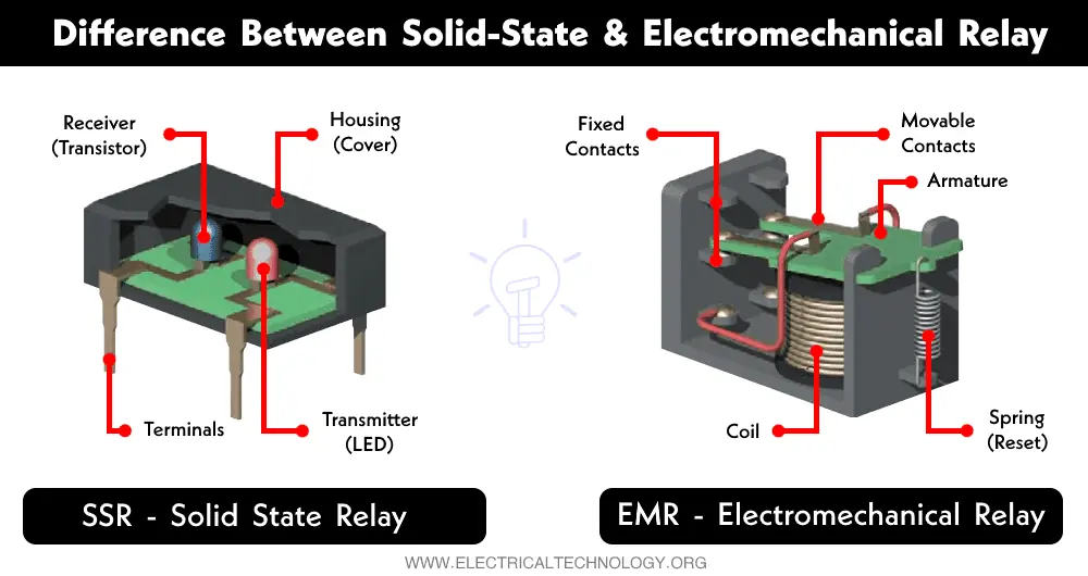
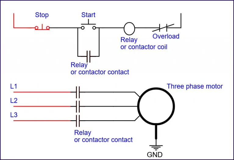
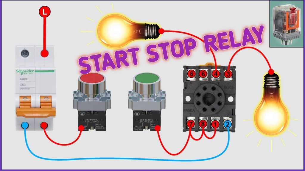
🔹Why You Should Include Start-Stop Logic in Your PCB Assembly

Built-In Safety and Control

Relays add simplicity. Instead of relying on software, your board includes core safety logic by default. Great for factories, field installations, and even IoT devices.

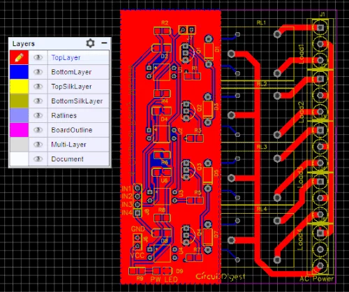
Turnkey PCB Assembly for Relay-Based Boards

At Unit Circuits, we specialize in relay logic PCB design and assembly. We help with:

  • Schematic design for start-stop logic

  • BOM sourcing for high-quality relays and buttons

  • Through-hole and SMT hybrid assembly

  • Final functional testing of relay behavior

Whether you need start stop relay PCB layout tips, or just want someone to build the board, we’ve got you covered.

From Prototyping to Production

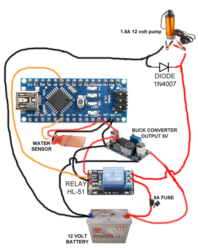
Our low-volume SMT assembly process makes it easy for startups and R&D teams to:

  • Iterate quickly

  • Try different relay configurations

  • Scale from 5 boards to 500+ without delays.After designing your start-stop relay PCB, make sure to validate functionality using these PCB testing methods.

5.start stop motor control panel relay
Start-Stop Relay Application in Motor Control Panel

FAQs

Start-stop circuits are inherently safe because they default to the “off” position during power loss, preventing accidental restarts. In industrial PCB design, this logic ensures controlled activation of motors or equipment, especially during maintenance or emergency shutdowns. Including this feature in PCB layout supports safety compliance and system reliability.

Before designing a start-stop relay circuit, beginners should understand how relay logic works, select suitable components (NO/NC buttons, relay ratings), and consider PCB design rules like trace width and isolation. Using circuit simulation tools and DFM (Design for Manufacturability) checks can help avoid costly redesigns.

To improve relay-based control PCB design, focus on optimized signal routing, proper power/ground separation, and thermal management. Include protection components like flyback diodes and fuse options. Using design software with electrical rule checks (ERC) helps identify errors early and improves production yield.

Reliable PCB circuit design follows principles like component placement optimization, clear signal flow, proper grounding, and thermal dissipation planning. For start-stop relay circuits, attention to mechanical relay specs, isolation between control and load, and fail-safe logic are key to performance and safety.

Have Specific Requirements?

Looking for high-precision PCB assembly for your products? Our team specializes in delivering top-tier assembly services, ensuring your devices perform flawlessly in any environment. Contact us today for a free consultation on how we can enhance your product’s reliability.

🟢Conclusion: Build Your Start-Stop Relay PCB with Confidence

Start-stop relay circuits are still one of the best ways to build reliable, maintainable, and scalable control systems. Whether you’re prototyping a custom relay PCB, scaling an automation panel, or launching a new IoT product, don’t overlook the power of embedded relay logic.

📩 Need expert help with a relay control board? Get a Free Quote from Unit Circuits.We’ll help you go from concept to control — fast.

Save on your next PCB project?

Claim $100 OFF your order today.

sales@unitcircuits.com

✅ high-quality PCB assembly with strict quality control ✅ ISO-certified & 8+ years of experience. ✅ Low MOQ, fast turnaround, and 100% E-tested PCBs.

Request for Quote

sales@unitcircuits.com

RECENT POSTS
Leading PCBA Manufacturer

✅ Assemble 20 PCBAS for $0 ✅ Get $100 OFF – Risk-Free Trial!

sales@unitcircuits.com

✅ 100+ Satisfied Customers

✅ Ensured Quality & On-Time Delivery

✅ Free Trial, No Commitments!

Leading PCBA Manufacturer

✅ Assemble 20 PCBAS for $0 ✅ Get $100 OFF – Risk-Free Trial!