
PCB silkscreen and solder mask serve different purposes. Solder mask is a protective polymer layer that covers PCB copper to prevent oxidation and solder bridging, while silkscreen is the printed identification layer used for component reference designators, symbols, polarity marks, logos, and other assembly information.
In simple terms: solder mask protects the PCB, while silkscreen helps identify and assemble it. Silkscreen is normally printed over the solder mask but should not overlap exposed pads or other solderable areas.
Quick Leads-PCBA
If you are new to this topic, it’s helpful to first understand the basics of silkscreen in PCB design. You can read our complete guide to PCB silkscreen to get a full overview of its function, materials, and applications.
What Is Solder Mask in PCB?
Solder mask in PCB design is a thin protective layer of polymer (usually liquid photoimageable epoxy) applied over copper traces.
Its primary role is to prevent solder bridges during assembly, protect copper from oxidation, and improve long-term electrical reliability.
PCB Solder Mask Material
Most modern boards use LPI (Liquid Photoimageable) solder mask, which offers high resolution for fine-pitch designs, strong adhesion, and consistent thickness.
PCB Solder Mask Process
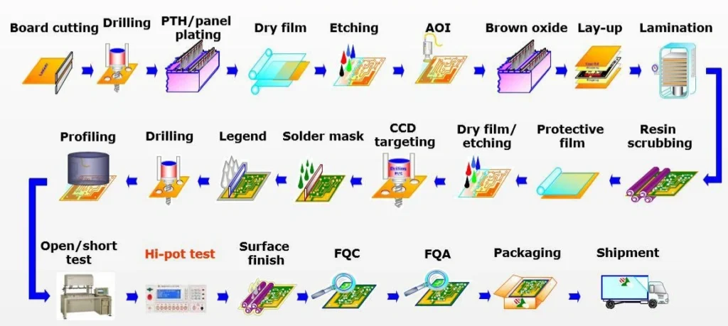
The solder mask process typically involves cleaning the PCB surface, applying a liquid epoxy coating, exposing it under UV light using a mask, and then developing and curing it. This step directly impacts manufacturing yield, especially in high-density designs.
Color Options
While green is the industry standard, solder mask colors also include black, red, blue, and white—often chosen for branding or visibility.
What Is PCB Silkscreen?
PCB silkscreen is a printed ink layer applied on top of the solder mask to display visual information for assembly and identification.
It doesn’t affect electrical performance, but it is essential for usability and manufacturing efficiency.
PCB Silkscreen Paint
Silkscreen typically uses epoxy-based ink, selected for durability, contrast, and resistance to soldering temperatures.
What Does Silkscreen Include?
- Component labels (R1, C1, U1)
- Polarity indicators
- Pin 1 markers
- Logos and instructions
If you want a deeper explanation, see: What is Silkscreen on PCB.
Application Methods
Silkscreen is applied using traditional screen printing or modern inkjet printing for higher precision.
To better understand how silkscreen works and why it matters in real PCB projects, refer to our detailed PCB silkscreen guide, which explains its role in both design and manufacturing.
PCB Silkscreen Symbols and Markings
PCB silkscreen symbols and markings help engineers, assemblers, and technicians identify components, polarity, orientation, connectors, test points, and other important information directly on the circuit board. Common markings include reference designators such as R for resistors, C for capacitors, D for diodes, and U for integrated circuits.
| Silkscreen Marking | Meaning |
|---|---|
| R | Resistor |
| C | Capacitor |
| D | Diode |
| Q | Transistor |
| U / IC | Integrated circuit |
| L | Inductor |
| J / CN | Connector |
| F | Fuse |
| TP | Test point |
| + / − | Polarity |
Note: Reference designators can vary by PCB design convention and company standards, so always verify the schematic, BOM, and assembly documentation when interpreting board markings.
For example, R12 typically identifies a resistor, while C5 identifies a capacitor. Polarity and orientation markings are especially important for components such as diodes, LEDs, electrolytic capacitors, and ICs because incorrect placement can cause assembly defects or circuit failure.
PCB Silkscreen vs Solder Mask (Detailed Comparison Table)
| Feature | Solder Mask | Silkscreen |
|---|---|---|
| Function | Prevents solder bridging, protects copper | Identifies components, reference designators, symbols, and markings |
| Material | Liquid photoimageable polymer | Epoxy-based ink |
| Location | Covers and protects copper areas except designated openings | Printed on top of solder mask |
| Electrical Role | Insulating and protective | No electrical function |
| Colors | Green, black, red, blue, white | Usually white (can vary) |
| Manufacturing Role | Critical for soldering reliability | Critical for assembly accuracy |
| Impact on Cost | Essential, affects yield and defects | Minimal cost impact |
| Pad Interaction | Openings expose pads and other solderable areas | Should not overlap exposed pads or solderable areas |
| Design Constraints | Mask expansion, dam width | Clearance, readability |

When Is Solder Mask Critical?
Solder mask is essential in modern PCB design, especially in complex boards.
Fine-Pitch Components
Packages like QFN and BGA require precise solder control. Without proper solder mask, the risk of solder bridging increases significantly.
High-Density Layouts
In HDI designs, tight spacing between traces makes solder mask dams critical to prevent electrical shorts.
Mass Production
Poor solder mask design can lead to low yield, increased rework, and long-term reliability issues—directly affecting production cost.
When Is Silkscreen Essential?
Silkscreen plays a key role in both manual and automated assembly.
Assembly Guidance
Clear labeling ensures correct component placement and orientation.
Maintenance and Debugging
Technicians rely on silkscreen to quickly identify components during troubleshooting.
Reducing Errors
Missing or unclear markings can slow down production and increase operator mistakes.
You can see more details here about What is PCB Silkscreen Used For.
How Silkscreen and Solder Mask Work Together
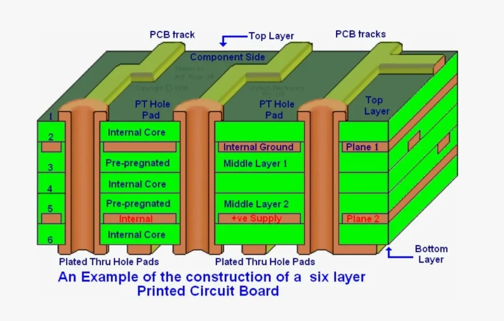
A PCB consists of multiple layers working together:
- Silkscreen (top ink layer)
- Solder mask (protective layer)
- Copper (conductive layer)
- Substrate (base material)
Simple Layer Diagram (Conceptual)
Silkscreen sits on top of the solder mask, while solder mask covers the copper traces beneath it.
Assembly Workflow
The solder mask controls where solder flows, while the silkscreen shows where components should be placed. Together, they ensure accurate assembly and reliable performance.
Why Is Silkscreen Clipped by Solder Mask?
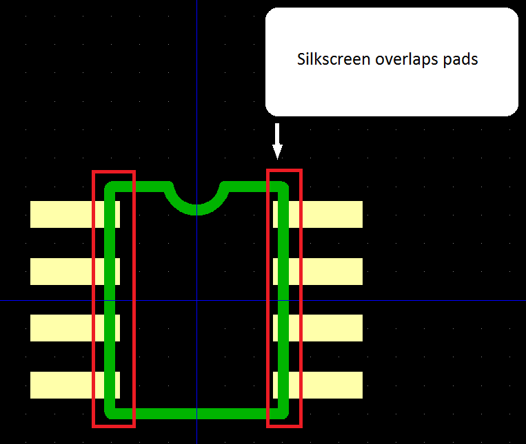
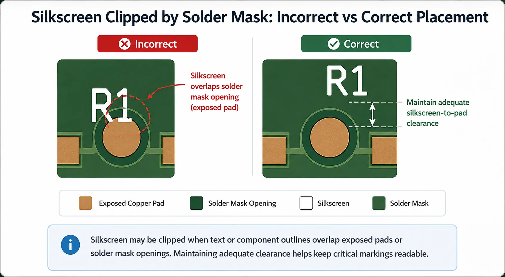
“Silkscreen clipped by solder mask” means that part of the PCB silkscreen text, symbol, or component outline overlaps a solder mask opening or exposed solderable area and may therefore be trimmed or removed during design-rule checking (DRC) or CAM processing.
This commonly happens when silkscreen is placed too close to exposed copper pads or other areas that must remain free of ink. During PCB manufacturing, conflicting silkscreen artwork may be automatically trimmed to prevent ink from covering solderable surfaces or interfering with soldering and electrical contact.
Common causes of clipped silkscreen include:
- Reference designators placed too close to pads
- Polarity symbols or text overlapping solder mask openings
- Component outlines crossing exposed solderable areas
- Insufficient silkscreen-to-pad clearance
How to Fix Silkscreen Clipped by Solder Mask
To fix clipped silkscreen, move important text, reference designators, symbols, and component outlines away from exposed pads and solder mask openings. Follow your PCB manufacturer’s recommended silkscreen-to-pad clearance and review the final Gerber files before production to confirm that critical markings remain readable.
PCB Design Considerations (Engineering Insights)
This is where many PCB designs succeed—or fail.
Silkscreen Clearance Rules
- Minimum clearance from pads: ≥ 4–6 mil (0.1–0.15 mm)
- Avoid placing silkscreen over vias or exposed copper
- Use CAD tools to clip overlapping silkscreen automatically
Minimum Text Size
- Recommended height: ≥ 40 mil (1.0 mm)
- Line width: ≥ 5–6 mil
Anything smaller may not be readable after fabrication.
Solder Mask Opening Considerations
- Typical expansion: +2 to +4 mil per side
- Minimum solder mask dam: ≥ 4 mil
Mask Types
- SMD (Solder Mask Defined): mask defines pad size
- NSMD (Non-Solder Mask Defined): copper defines pad size
NSMD is commonly used for fine-pitch components.
Common Layout Conflicts
- Silkscreen overlapping pads
- Mask openings too large (causing solder spread)
- Mask too tight (leading to poor solder wetting)
Common PCB Design Mistakes to Avoid
Silkscreen Printed Over Pads
This can contaminate solder joints and lead to poor electrical connections.
Missing Solder Mask Between Pins
Especially critical for fine-pitch ICs, this can result in short circuits.
Ignoring Manufacturer Design Rules
Each PCB manufacturer has specific limits for solder mask and silkscreen. Ignoring them often leads to fabrication issues.
Can a PCB Work Without Solder Mask?
Technically, yes—but it is rarely practical.
Without solder mask:
- Risk of short circuits increases
- Copper is exposed to oxidation
- Solder control becomes difficult
Such designs are usually limited to simple prototypes or non-critical applications.
What Happens If Silkscreen Overlaps Pads?
This is a common but serious design issue.
Consequences
- Ink can burn during soldering
- Contaminates solder joints
- Leads to weak or failed connections
Most manufacturers will either remove the overlapping silkscreen or reject the design.
What Is Solder Mask Opening in PCB Design?
A solder mask opening is the area where copper is intentionally exposed for soldering.
Why It Matters
- Controls solder paste deposition
- Affects joint quality
- Influences stencil design
Poorly designed openings can cause insufficient solder, bridging, or defects like tombstoning.
Manufacturing Perspective: How These Layers Are Applied
Solder Mask Application
The board is coated with liquid photoimageable solder mask, exposed under UV light, and then cured. This step is critical for electrical insulation and production yield.
Silkscreen Printing
Silkscreen is applied after the solder mask using screen or inkjet printing. It has minimal electrical impact but is vital for assembly.
Cost and Yield Impact
Poor solder mask design can directly reduce manufacturing yield. Poor silkscreen design, while less critical electrically, can slow assembly and increase errors.
FAQs
1. What is the main difference between PCB silkscreen and solder mask?
The main difference is their function. Solder mask is a protective insulating layer applied over copper traces to prevent oxidation and solder bridging, while PCB silkscreen is a printed ink layer used to label components, symbols, and assembly instructions for easier identification and debugging.
2. Can a PCB work without solder mask?
Technically, a PCB can function without solder mask, but it is not recommended. Without it, copper traces are exposed, increasing the risk of oxidation, short circuits, and solder bridging. Solder mask is essential for reliable and stable PCB performance, especially in mass production.
3. Can silkscreen be printed directly on copper?
In most cases, silkscreen should not be printed directly on exposed copper. Silkscreen ink is normally applied over the solder mask, not over bare copper pads, fingers, test points, or contact areas. Printing ink on exposed copper may affect solderability, electrical contact, surface finishing, or inspection.
Some non-functional copper areas may technically accept printing, depending on the board finish and manufacturing process, but this should be confirmed with the PCB manufacturer. As a general design rule, keep PCB silkscreen away from exposed copper and place markings on the solder mask surface whenever possible.
4. What happens if silkscreen is printed on pads?
If silkscreen overlaps with pads, the ink can interfere with soldering, leading to poor solder joints or assembly defects. Most PCB manufacturers automatically remove silkscreen from pads during processing, but designers should avoid this issue by following proper clearance rules.
5. What clearance is required between silkscreen and solder mask?
The required silkscreen-to-solder-mask clearance depends on the PCB manufacturer’s equipment, registration tolerance, and design rules. In practice, silkscreen should be kept far enough away from exposed pads and solder mask openings to prevent clipping or ink contamination.
Rather than relying on one universal value, designers should follow the PCB supplier’s published capabilities. For dense layouts, confirm the minimum clearance before releasing Gerber files. Important markings such as polarity indicators, Pin 1 symbols, and reference designators should also be positioned with extra space so they remain visible after fabrication and assembly.
Have Specific Requirements?
Looking for high-precision PCB assembly for your products? Our team specializes in delivering top-tier assembly services, ensuring your devices perform flawlessly in any environment. Contact us today for a free consultation on how we can enhance your product’s reliability.
Summary
Understanding PCB silkscreen vs solder mask is essential for both design accuracy and manufacturing success. One protects your circuit, while the other guides assembly. When used correctly together, they reduce errors, improve yield, and ensure reliable PCB production.
While solder mask ensures electrical protection and manufacturing reliability, silkscreen plays a critical role in improving assembly accuracy and reducing human error. For a complete understanding of PCB silkscreen, including design rules, materials, and common applications, explore our full guide to PCB silkscreen.Final Insight
In real-world manufacturing, even small details—like silkscreen clearance or solder mask expansion—can determine whether your design scales smoothly.
If you’re moving from prototype to mass production, aligning your design with professional PCB fabrication and assembly capabilities early can prevent costly iterations and delays.
Request for Quote
sales@unitcircuits.com
RECENT POSTS
What Are PCB Silkscreen Design Guidelines? (Clearance, Font Size & DFM Rules Explained)
Learn PCB silkscreen design guidelines, including font size, clearance, and DFM rules. Improve readability, prevent
What Is PCB Silkscreen Used For? Functions, Symbols & Practical Examples
Learn what PCB silkscreen is used for, including symbols, functions, and real applications. Improve assembly
RELATED POSTS
Leading PCBA Manufacturer
✅ Assemble 20 PCBAS for $0 ✅ Get $100 OFF – Risk-Free Trial!
sales@unitcircuits.com
✅ 100+ Satisfied Customers
✅ Ensured Quality & On-Time Delivery
✅ Free Trial, No Commitments!

 Assemble 20 PCBAS for $0