Looking for a reliable PCB assembly manufacturer? Turnkey solutions from PCB Manufacturing, Components Sourcing, PCB Assembly to Function Testing.
 ISO-certified & 8+ years of PCBA Low MOQ & Fast Turnaround Prototype & Mass production
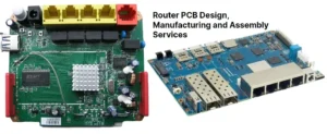
Who Are the Top 10 Router PCBA Manufacturers for OEM Projects (Fast Turnkey & Low MOQ)?
Find a reliable router PCBA manufacturer for OEM projects with turnkey assembly, RF expertise, and
Who Are the Top 10 Gas Detection Equipment Manufacturers & EMS Suppliers in 2026?
Explore top gas detection equipment manufacturers and discover how advanced PCB assembly services improve reliability,