
PCB silkscreen is a non-conductive printed layer on a printed circuit board (PCB) used to display component reference designators, symbols, polarity marks, test points, logos, and assembly information. It is typically printed on top of the solder mask and helps engineers, assemblers, and technicians identify components and assemble, inspect, and troubleshoot the PCB.
Unlike copper traces, PCB silkscreen has no electrical function. Its primary role is identification and communication during PCB assembly, inspection, testing, and maintenance.
This guide explains what PCB silkscreen is, what information it contains, where it is located, the materials and printing methods used, and the key design rules engineers should consider before PCB manufacturing.
Quick Leads-PCBA
What Is Silkscreen on a PCB?
PCB silkscreen, also called the legend or legend layer, consists of printed text, symbols, numbers, and reference designators on the top or bottom surface of a circuit board. Common markings include component IDs such as R1, C5, and U2, polarity indicators, Pin 1 markers, connector labels, test-point labels, logos, and assembly instructions.
The term “silkscreen” comes from the traditional screen-printing process. Modern PCB manufacturers may use other printing technologies, but “silkscreen” remains the standard industry term for this identification layer.
What Is the Purpose of Silkscreen in PCB?
The PCB silkscreen serves several essential functions:
- Component identification (R1, C5, U2)
- Assembly guidance for technicians and machines
- Debugging and maintenance support
- Polarity marking to prevent incorrect placement
- Branding and compliance labeling
For a more detailed explanation of these functions and their role in PCB manufacturing and assembly, see our guide on what PCB silkscreen is used for.
Where Is Silkscreen Located on a PCB?
PCB silkscreen is typically applied to:
- The top layer (top silkscreen)
- The bottom layer (bottom silkscreen)
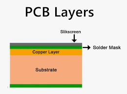
Silkscreen is typically printed over the solder mask on the top and/or bottom surface of the PCB. It is a non-conductive identification layer and should not cover exposed pads or other solderable areas.
Top vs. Bottom PCB Silkscreen
Top PCB silkscreen is printed on the component side of the board and is the most commonly used layer for reference designators, polarity marks, company logos, and assembly instructions. Bottom PCB silkscreen is applied when components are mounted on the opposite side, helping technicians identify parts during assembly, inspection, and maintenance. Depending on the PCB design, a board may use only the top silkscreen or both layers. Before manufacturing, always verify the correct silkscreen layer in your Gerber files to prevent misplaced markings.
What Material Is Used for PCB Silkscreen?
The PCB silkscreen ink used must be durable, precise, and non-conductive.
Common materials:
Epoxy Ink
- Standard in most boards
- Cost-effective and durable
Liquid Photoimageable (LPI)
- Higher resolution
- Suitable for dense layouts
Inkjet / Direct Legend Printing
- Advanced PCB silkscreen printer method
- High precision and flexibility
These silkscreen PCB materials impact resolution, cost, and manufacturability.
Common PCB Silkscreen Colors
Although white is the most widely used PCB silkscreen color, manufacturers also offer black, yellow, and other colors for specific solder mask combinations. The primary purpose of choosing a silkscreen color is to maximize readability rather than improve electrical performance. A high-contrast combination, such as white on green or black solder mask, makes reference designators and polarity marks easier to identify during assembly and inspection.
Related Guide: Learn how different printing processes affect silkscreen quality in our PCB Silkscreen Printing Methods guide.
PCB Silkscreen Guidelines (Design for Manufacturability)
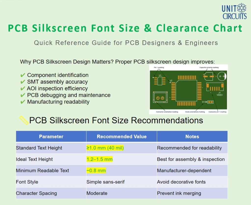
PCB silkscreen capabilities vary by manufacturer, printing process, font style, and board design. The following values are general design guidelines for improving readability and manufacturability:
- Minimum text height: ≥ 0.8 mm preferred for readability
- Minimum line width: ≥ 0.1 mm
- Silkscreen-to-pad clearance: ≥ 0.15 mm
- Avoid silkscreen over exposed solderable pads and solder mask openings
- Keep reference designators and polarity markings clear and consistently oriented
Note: These values are general PCB design references rather than guaranteed manufacturing limits. Actual capabilities may vary depending on the fabrication process and PCB manufacturer.
What Is the Minimum PCB Silkscreen Font Size?
A PCB silkscreen text height of 0.8 mm or larger is generally preferred for good readability, while text around 0.6 mm may be achievable with some PCB manufacturing processes. However, the minimum printable text size depends on the font style, stroke width, printing method, and manufacturer’s capabilities.
For critical reference designators, polarity markings, and assembly information, prioritize readability rather than designing to the absolute manufacturing minimum.
Explore practical PCB silkscreen engineering resources, including font size charts, DFM checklists, and manufacturing reference guides for PCB designers and engineers.
What Are PCB Silkscreen Clearance Rules?
As a general design guideline, maintaining approximately 0.15 mm or more between silkscreen markings and exposed pads can help reduce the risk of clipping or ink entering solderable areas.
Silkscreen text, symbols, and component outlines should also avoid solder mask openings and maintain adequate clearance from vias where required. Exact clearance requirements vary by PCB manufacturer and fabrication process.
If silkscreen overlaps an exposed pad or solder mask opening, part of the marking may be clipped or removed during CAM processing.
Can Silkscreen Be Placed on Pads or Vias?
Silkscreen should generally not be placed over exposed solderable pads, as the ink may interfere with soldering or obscure critical pad areas.
Silkscreen placement over vias depends on the via design and manufacturing process. Markings that conflict with exposed pads, solder mask openings, or other restricted areas may be clipped or removed during CAM preparation.
Always review the final Gerber files and confirm manufacturer-specific clearance requirements before production.
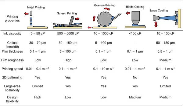
PCB Silkscreen Printing Methods
Modern PCB silkscreen printing methods include:
Screen Printing
- Traditional
- Cost-effective for volume
LPI Process
- High-resolution imaging
Inkjet Printing
- Advanced PCB silkscreen printer technology
- Ideal for complex designs
How Does PCB Silkscreen Help Assembly and Inspection?
PCB silkscreen provides a visual reference that helps technicians and engineers identify components, verify orientation, inspect assembled boards, and troubleshoot PCB assemblies.
During manual assembly and inspection, clear reference designators, polarity marks, Pin 1 indicators, and connector labels can make component identification faster and reduce the risk of placement or orientation errors.
PCB silkscreen does not control automated pick-and-place equipment, which normally relies on PCB assembly data such as component coordinates and placement files. Likewise, AOI systems primarily inspect programmed board features rather than relying solely on silkscreen markings.
However, clear and accurate silkscreen remains valuable for manual inspection, rework, debugging, maintenance, and quality verification throughout the PCB assembly process.
Common PCB Silkscreen Mistakes to Avoid
Frequent PCB silkscreen mistakes include:
- Overlapping pads
- Missing labels
- Poor contrast
- Cluttered layout
- Inconsistent marking styles
What Information and Symbols Are Printed on PCB Silkscreen?
Common PCB Silkscreen Symbols
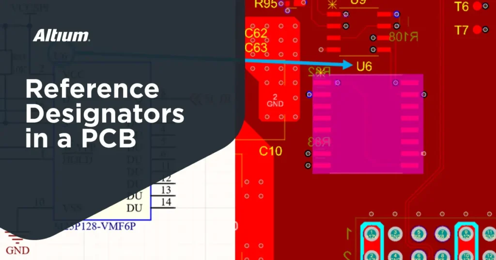
PCB silkscreen symbols help engineers, assemblers, and technicians identify components, polarity, orientation, connectors, and test points directly on the circuit board. Common markings include reference designators such as R1, C5, D2, and U3, as well as Pin 1 indicators, polarity symbols, and connector labels.
Common PCB silkscreen reference designators include:
| Marking | Common Meaning |
|---|---|
| R | Resistor |
| C | Capacitor |
| D | Diode |
| Q | Transistor |
| U / IC | Integrated circuit |
| L | Inductor |
| J / CN | Connector |
| F | Fuse |
| TP | Test point |
| + / − | Polarity |
For example, R12 typically identifies a resistor, while C5 identifies a capacitor. Pin 1 and polarity markings are especially important for components such as ICs, diodes, LEDs, and polarized capacitors because incorrect orientation can cause assembly errors or circuit failure.
Note: Reference designators and marking conventions may vary depending on the PCB design standard, company practice, and schematic. Always verify the schematic, BOM, and assembly documentation when interpreting PCB markings.
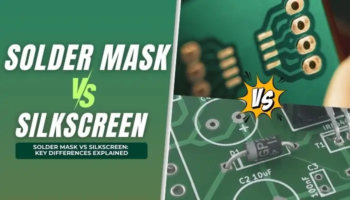
PCB Silkscreen vs Solder Mask
Understanding PCB silkscreen and solder mask differences:
- Silkscreen: informational layer
- Solder mask: protective insulating layer
They serve completely different roles in PCB design and manufacturing. For a detailed comparison of their functions, materials, design requirements, and manufacturing impact, see our PCB Silkscreen vs Solder Mask guide.
PCB Silkscreen vs Copper Layer
- PCB silkscreen: non-conductive, informational
- Copper layer: conductive, functional
Mixing these concepts can lead to serious design issues.
What Is PCB Silkscreen Thickness?
PCB silkscreen is a thin printed ink layer on the board surface. A typical silkscreen thickness may be approximately 10–25 μm, although the actual thickness varies depending on the ink, printing method, curing process, and PCB manufacturer’s process capabilities.
For most PCB designs, silkscreen thickness is less important than print resolution, text readability, line width, adhesion, and correct placement. Designers should therefore focus primarily on clear markings and manufacturable silkscreen geometry rather than specifying an exact ink thickness unless the application has special requirements.
How to Ensure Your PCB Silkscreen Is Manufacturing-Ready
To optimize PCB silkscreen for production:
- Run DRC checks
- Follow PCB silkscreen guidelines
- Ensure readability after assembly
- Maintain proper spacing
- Optimize contrast
Working with an experienced PCB manufacturer helps validate PCB silkscreen during CAM review, improving yield and reducing errors.
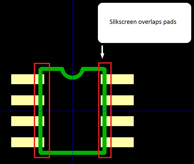
Practical Example: Good vs Bad PCB Silkscreen Design
A well-designed PCB silkscreen uses clear reference designators, readable text, consistent component orientation, and sufficient clearance from exposed pads and solder mask openings. Important markings such as polarity indicators and Pin 1 symbols should remain visible after component assembly.
In contrast, poor silkscreen design may include text that overlaps pads, reference designators hidden beneath components, unreadable characters, or missing polarity and orientation markings. These issues may not affect the electrical circuit directly, but they can make assembly, inspection, debugging, and maintenance more difficult.
Before PCB production, check the final Gerber files to confirm that critical silkscreen markings are readable, correctly positioned, and clear of solderable areas.
FAQs
1. What are the disadvantages of silkscreen printing in PCB assembly?
While silkscreen printing in PCB assembly helps with labeling and component identification, its disadvantages include limited resolution with manual screen printing, potential misalignment on small-pitch boards, and added cost for double-sided silkscreen. For precision assemblies, Direct Legend Printing (DLP) is often preferred. If you’re sourcing custom PCB silkscreen service in China, ask your vendor about print resolution, registration accuracy, and options for no MOQ PCB silkscreen to avoid surprises.
2. How thick is the silkscreen on a PCB and why does it matter?
The silkscreen thickness on a PCB typically ranges between 5 to 15 microns, depending on the printing method and ink type. Why does it matter? Excessive thickness can interfere with soldering or create clearance issues, especially on high-density boards. That's why our team double-checks the silkscreen layer in PCB design during our DFM review to ensure optimal print quality without sacrificing assembly performance.
3. What are the available PCB silkscreen colors and how do I choose?
White is the most common silkscreen color due to its high contrast on green solder mask. Other options include yellow, black, and red, often used to match branding or improve visibility. When selecting PCB silkscreen colors, consider the readability under lighting, production contrast, and even your brand identity. We offer custom PCB silkscreen with multiple ink color options — no extra charge for low-volume orders.
4. What is the difference between silkscreen and screen printing in PCB production?
In PCB production, silkscreen refers to the printed reference layer on the board surface, while screen printing is one of the methods used to apply that layer. Confused? Think of silkscreen as the result, and screen printing as one way to achieve it. Other methods include LPI and inkjet printing, which offer better precision for complex boards. Our production line uses multiple technologies depending on board specs and your PCB assembly process requirements.
Need Help Reviewing Your PCB Design for Manufacturing?
If you are preparing a PCB or PCBA project for production, our team can review your Gerber files, BOM, and assembly requirements before quotation. We support PCB manufacturing, component sourcing, and PCB assembly for prototype and production projects.
Send us your Gerber files and BOM for a fast quotation and manufacturing review.
Request for Quote
Summary
PCB silkscreen is the non-conductive identification layer printed on a circuit board to show reference designators, component symbols, polarity marks, test points, logos, and assembly information. Although it does not perform an electrical function, clear silkscreen improves PCB readability and supports assembly, inspection, troubleshooting, and maintenance.
For a manufacturing-ready design, use readable text and line widths, maintain sufficient clearance from exposed pads and solder mask openings, keep important markings visible after assembly, and review the final Gerber files before production.
Related PCB Silkscreen Topics:
- What Are PCB Silkscreen Design Guidelines? (Clearance, Font Size & DFM Rules Explained)
- What Is PCB Silkscreen Used For? Functions, Symbols & Practical Examples
- PCB Silkscreen vs Solder Mask: Key Differences, Functions & Design Tips
- What Are the Most Common PCB Silkscreen Mistakes (and How to Avoid Them)?
- What Are PCB Silkscreen Printing Methods and Which One Should You Choose?
RECENT POSTS
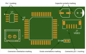
What Are PCB Silkscreen Design Guidelines? (Clearance, Font Size & DFM Rules Explained)
Learn PCB silkscreen design guidelines, including font size, clearance, and DFM rules. Improve readability, prevent
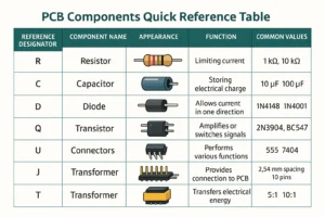
What Is PCB Silkscreen Used For? Functions, Symbols & Practical Examples
Learn what PCB silkscreen is used for, including symbols, functions, and real applications. Improve assembly
RELATED POSTS
Leading PCBA Manufacturer
✅ Assemble 20 PCBAS for $0 ✅ Get $100 OFF – Risk-Free Trial!
✅ 100+ Satisfied Customers
✅ Ensured Quality & On-Time Delivery
✅ Free Trial, No Commitments!

 Assemble 20 PCBAS for $0